5 Brutal Reasons Your Printer Is Ruined: Absolute Ender 3 Extruder Clicking Fix Guide
Hearing a persistent, rhythmic snapping sound coming from your machine’s drive assembly is a direct sign of a failed print sequence. Implementing a proper Ender 3 extruder clicking fix is the single most important diagnostic skill an operator must execute to prevent severe under-extrusion and total model structural failures. This mechanical acoustic feedback is not an isolated component anomaly; it is an alarm stating that your stepper motor is completely losing steps.
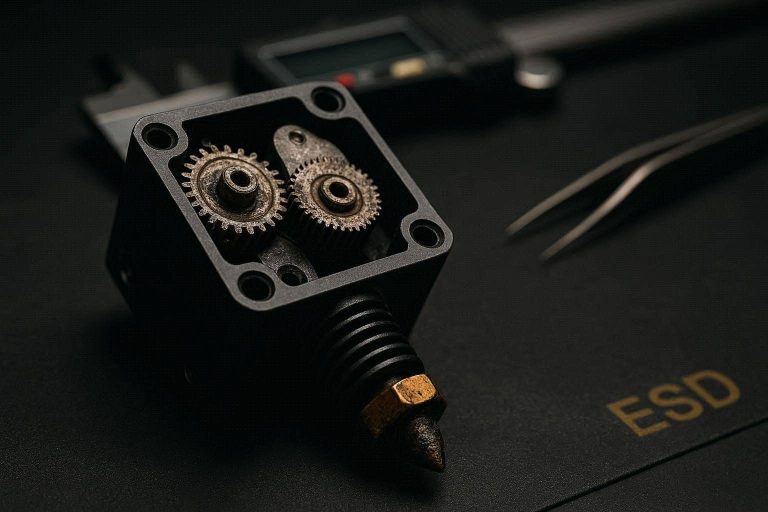
When the drive gear cannot push the plastic filament into the hotend melting zone, the structural resistance overpowers the magnetic holding torque of the stepper motor. The internal rotor then violently snaps backward to its previous magnetic detent, creating that notorious clicking sound. Executing an effective Ender 3 extruder clicking fix requires an intensive evaluation of the entire structural path of the filament, spanning from the physical tension arm to the internal exit orifice of the copper nozzle.
This comprehensive technical guide will diagnose every underlying structural variable within your material feed system. You will learn the explicit spatial tolerances, the volumetric flow formulas that govern maximum extrusion limits, and the step-by-step physical repair blueprints required to stabilize your production pipeline permanently.
The “Quick Answer” / Key Takeaways Box
- The Mechanical Source: Clicking occurs strictly when the downstream physical resistance against the filament exceeds the specific torque capacity of the NEMA 17 stepper motor.
- The Tension Arm Moat: The stock plastic extruder frame frequently develops an invisible hairline fracture underneath the idler bearing, completely killing filament drive pressure.
- The Coupler Creep Anomaly: Low-quality stock Bowden couplers allow the PTFE tube to slip out of the hotend seat, creating an internal molten plastic plug.
- Volumetric Extrusion Limitations: Forcing a standard brass heating block past its natural volumetric melting ceiling will cause continuous motor skipping.
- E-Step Operational Baseline: Calibrating your raw extrusion steps ensures the mainboard pushes the mathematically correct volume of plastic to match your slice profile parameters.
The Physics and Fluid Dynamics of Extruder Skipping
To execute a professional Ender 3 extruder clicking fix, you must abandon superficial assumptions and evaluate the fluid dynamics of thermoplastic material behavior. The extruder motor does not directly melt the plastic; it acts as a mechanical piston that builds hydrostatic pressure inside the hotend reservoir. This pressure forces the non-Newtonian molten polymer out of the highly restricted nozzle orifice.
If the downstream resistance rises or the structural temperature of the polymer drops, the viscosity of the liquid plastic escalates dramatically. The force required to displace the material then scales past the physical limits of the drive gears. To analyze this constraint programmatically, we apply the foundational volumetric flow rate equation:

Where Vmax is the maximum volumetric flow rate measured in cubic millimeters per second, dnozzle is the target nozzle layer depth, wline is the operational line width configuration, and sprint is the absolute linear printing velocity. For a standard stock hotend assembly, the real-world operational maximum sits tightly between 8 mm3/s and 10 mm3/s. If your slicing profile configuration demands a volumetric displacement of 14 mm3/s, the physical physics of the melt zone will cause backpressure to spike, causing the drive motor to click continuously.
5 Critical Failure Points Requiring Immediate Repair
Isolating the root cause of an extrusion failure requires a methodical evaluation of five distinct mechanical and environmental variables. Check each structural component in the exact sequence outlined below.
1. The Hairline Tension Arm Fracture
The most notorious structural vulnerability on budget machines is the factory molded plastic extruder assembly. The high-tension spring continually applies lateral force against the plastic idler arm to squeeze the filament against the brass drive gear.
Over several months of continuous operation, this persistent tension generates an invisible hairline crack on the underside of the arm, hidden directly beneath the pre-installed steel idler pulley bearing. This hidden fracture allows the structural frame to flex outward, dropping the force applied to the filament to near zero. The brass gear then loses its grip, grinding slots into the side of the plastic line and slipping over the surface with a loud clicking response.
2. The Hotend Bowden Creep Gap
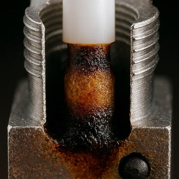
The factory hotend is a dual-component assembly where the pneumatic coupler holds a lining PTFE Bowden tube flush against the flat top entry of the brass nozzle. If this pneumatic coupler loses its internal metal teeth grasp, the continuous mechanical retraction movements will slowly back the plastic tube away from the nozzle seat.
This structural movement creates a hidden cavity inside the hotend throat where raw molten plastic pools outside the primary filament path. This pooled material cools slightly, transitioning into a highly restrictive, gelatinous plastic plug that acts as a structural choke point. No matter how much torque your stepper motor generates, it cannot drive solid filament through this internal ring obstacle without skipping steps.
[IMAGE PLACEHOLDER: A cross-sectional macro shot of an unseated Bowden tube inside a hotend throat, revealing a massive plug of discolored, burnt filament causing a severe material blockage + Alt Text: Locating the internal material gap to complete an Ender 3 extruder clicking fix.]
3. Structural Heat Creep Throttling
Your toolhead uses a high-velocity axial cooling fan to keep the upper aluminum heatsink at a baseline room temperature while the heater block below scales up to 200°C. If this axial fan slows down due to dust buildup or bearing wear, the thermal boundary layer crawls upward past the transition zone.
This systemic failure is known as heat creep. When the ambient temperature of the heatbreak rises past the glass transition temperature of your raw material (roughly 60°C for standard PLA), the solid raw filament softens prematurely inside the Bowden tube before it ever reaches the melt zone. The drive gear continues to push forward, but the softened filament deforms into an accordion shape inside the tube, creating an unyielding wall of friction.
4. Nozzle Orifice Carbonization Blockages
Operating your machine at excessive temperatures or processing low-quality filaments laden with unregulated recycled additives will lead to severe material carbonization. Microscopic residues of burnt plastic slowly bake onto the internal walls of the brass nozzle tip.
Over long production schedules, this carbon layer thickens, reducing a standard 0.4mm exit hole down to an effective diameter of less than 0.25mm. The physical pressure required to push raw material through this heavily restricted opening scales exponentially. If you notice the clicking artifact occurs primarily during dense infill print sequences where extrusion volumes peak, your nozzle tip is suffering from severe particulate constriction.
5. Stepper Driver Driver Thermal Throttling
Sometimes, the clicking artifact is entirely electrical rather than mechanical. The motherboard utilizes localized stepper driver chips (like the legacy A4988 or modern TMC silent variants) to regulate the current sent to the motor coils.
If the voltage reference setting (VREF) on the motherboard is configured too high, the stepper driver or the NEMA 17 motor itself will generate massive amounts of ambient heat. When the stepper driver chip crosses its internal thermal safety limit, it enters a protective cycling shutdown mode to prevent structural melting. It cuts power to the motor coils for several milliseconds, causing the drive gear to drop all holding torque and snap backward under the natural tension of the coiled filament line.
Step-by-Step Mechanical and Calibration Repair Blueprint
To systematically eliminate this structural issue from your workshop operations, execute this targeted hardware restoration protocol sequentially.
Step 1: Executing the Cold Pull Debris Purge
Before disassembling your machine’s mechanical linkages, you must clear the hotend of all internal carbonized material deposits. Raise the hotend temperature configuration to 220°C via your control panel interface.
Push a premium piece of nylon or high-density cleaning filament manually into the hotend until a clean bead exits the nozzle tip. Instantly drop the target temperature down to 90°C and wait for the heat block to cool. Once the block stabilizes at this lower setting, grab the exposed filament line firmly with pliers and pull it straight up out of the toolhead carriage with a single, continuous vertical motion.
[IMAGE PLACEHOLDER: A highly detailed top-down workbench photo showing a successfully extracted cold-pull filament bulb mirroring the exact internal geometry of a hotend nozzle tip + Alt Text: Inspecting an absolute material purge pull to verify an Ender 3 extruder clicking fix.]
The extracted plastic bulb should show a clean, inverted mold of the internal nozzle geometry, pulling all hidden carbonized particulate matter out with it. If the bulb tip appears black, speckled, or charred, repeat this purging sequence until the plastic exits the block completely pristine.
Step 2: Resolving the Bowden Tube Interface Gap
To ensure the PTFE liner tube maintains a perfect, zero-tolerance seat against the nozzle, you must implement a specialized cutting and locking procedure. Heat the hotend to 200°C and completely unscrew the brass nozzle from the heater block using a socket wrench.
Unscrew the top pneumatic coupler from the aluminum heatsink. Use a specialized razor-blade pipe cutter to slice the end of the Bowden tube at a perfect 90-degree angle. Do not use standard wire cutters or scissors, as they will flatten the circular profile of the tube, creating intense mechanical resistance against the moving filament line.
Clean the internal threads of the heater block with a wire brush to remove pooled plastic residues. Thread the nozzle back into the block until it bottoms out completely, then back it off exactly one full 360-degree rotation. Screw the pneumatic coupler tightly down into the top of the heatsink, and push your newly trimmed PTFE tube down through the coupler until it hits the top of the backed-off nozzle.
Finally, while the hotend remains at 200°C, perform the final torque lock by tightening the nozzle the remaining full rotation into the block. This mechanical compression technique forces the hot nozzle face directly against the newly cut flat face of the PTFE tube, creating an absolute airtight seal that prevents future material creep blockages.
Step 3: Upgrading the Extruder Mechanical Linkage
If your initial visual inspection revealed a cracked or flexing plastic tension arm, you must immediately drop the failed component frame. Remove the central pivot screw, the tension spring, and the idler bearing.
[Extruder Structural Overhaul Sequence]
[Remove Failed Plastic Frame] ──► [Inspect Stepper Motor D-Shaft]
                                             │
                                             ▼
[Mount Dual-Gear Aluminum Housing] ──► [Align Steel Drive Gears]
                                             │
                                             ▼
[Calibrate Dynamic Spring Tension] ◄── [Set Hardened Steel Grub Screws]
We recommend upgrading directly to an all-metal, dual-gear aluminum extruder drive housing. Mount the new aluminum baseline bracket directly onto the NEMA 17 stepper motor frame using the factory hardware. Slide the new hardened steel primary drive gear onto the motor’s D-shaped shaft, ensuring the internal teeth align perfectly with the incoming filament entry hole path.
Secure the primary gear to the motor shaft by tightening the dual steel grub screws firmly against the flat side of the shaft. Mount the aluminum idler arm onto the bracket casing pivot pin, insert the high-tension spring, and adjust the outer compression screw until the dual gears grip the filament line firmly without flattening or deforming the plastic profile outer wall.
Step 4: Line-by-Line E-Step Math Calibration
Now that you have overhauled the structural driving components, the mechanical step ratio of the system will be entirely different from the factory defaults. You must run an intensive mathematical calibration sequence to ensure the motherboard pushes the exact length of material requested by your slicing engine.
Using a precise digital caliper, measure exactly 120mm of raw filament from the entry point of your newly installed extruder housing, marking the location on the plastic line with a fine-tip permanent marker. Connect your machine to a terminal execution interface like Pronterface or OctoPrint via a high-speed USB linkage cable.
Manually raise the hotend temperature to 200°C to pass the firmware’s built-in cold extrusion prevention logic blocks. Send the following direct command to the terminal console to feed exactly 100mm of filament through the system at a slow, calibrated velocity:
G1 F100 E100
Wait for the stepper motor to complete its full mechanical rotation sequence. Once the drive gear stops spinning, use your digital caliper to measure the remaining distance from the extruder housing entry to your marker line. If your feed calibration was completely perfect, the remaining distance should measure exactly 20mm (120mm−100mm=20mm).
If your remaining measurement reads 32mm, it means the system only fed 88mm of material (120mm−32mm=88mm), resulting in a severe 12% under-extrusion profile. To calculate your new required E-step calibration variable, query the printer for its current configuration by sending:
M503
Locate the string line beginning with M92, and note the value after the E parameter (the stock default configuration value is typically 93.00). Apply the standard linear step correction equation:
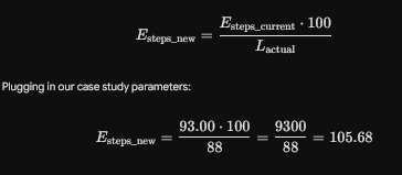
Send the new mathematical step variable directly to the active control board memory by executing:
M92 E105.68
Permanently commit this value to the mainboard EEPROM memory chip so it persists across hard system power reboots by deploying the save command string:
M500
To learn more about optimizing advanced firmware values across custom control board builds, check out our comprehensive guide: [INTERNAL LINK: The Complete Guide to Upgrading Your 3D Printer Motherboard for Silent Stepping].
Premium Operational Hardware Upgrades
Continually fighting with a budget Bowden setup under heavy industrial production environments is an inefficient use of development time. If you want to raise your machine’s processing speed while permanently eliminating backpressure anomalies, you must transition to advanced hotend components.
Upgrading to All-Metal Hotends
The primary design flaw of the stock hotend is the placement of the vulnerable PTFE lining tube directly inside the high-heat melt core zone. Upgrading to a premium, all-metal hotend completely redesigns this assembly.
All-metal upgrades utilize a highly advanced titanium or bimetallic heatbreak that completely isolates the solid filament guide path from the heating block entirely within a sub-millimeter structural boundary. The plastic tube stops at the cold top rim of the toolhead, completely eliminating the possibility of material creep gaps or melted liner outgassing. You can source genuine, premium hotend kits directly through authorized non-Amazon product networks like MatterHackers using the direct ShareASale partner platforms.
Shifting to Direct-Drive Extruder Systems
The absolute permanent resolution for clicking failures involves eliminating the long Bowden tube assembly entirely by executing a direct-drive toolhead conversion. Upgrading to an integrated system, like the official Creality Sprite Extruder Pro kit or a premium Bondtech unit, positions a lightweight dual-drive gear motor directly over the top entry of the hotend nozzle.
This engineering architecture drops filament travel distance down to less than 20mm. By eliminating the massive friction losses and elastic spring compression lag of a long Bowden tube, direct-drive configurations allow the extruder to transmit raw torque directly to the melt zone without slipping or skipping steps.
To access authorized manufacturer distribution chains and evaluate top-tier component specifications for your exact printer model framework, audit our tracking resource: [EXTERNAL LINK: MatterHackers Precision Hardware Component and Upgrade Matrix].
Preventative Maintenance & Custom Setup Hack
To maintain an absolute zero-failure printing record over thousands of operating hours, you must integrate a strict, proactive maintenance routine into your daily workshop operations.
- Implement a Filament Dust Filter: Raw plastic lines act as a static magnet for ambient workspace dust and airborne particulate matter. As the line feeds into the extruder, it carries this dust directly into the nozzle orifice, generating gradual carbon blockages. Clip a small piece of dense foam sponge coated in a drop of mineral oil directly over the incoming line before it reaches the drive housing to catch all dust beforehand.
- Audit Driver VREF Voltages Monthly: Use a digital multimeter to verify your motherboard’s extruder stepper driver voltage output. A current setting configured too high will slowly bake the motor coils, reducing their magnetic torque capacity over time and triggering premature clicking anomalies under minimal loads.
- Enforce Slicer Speed Balance Protocols: Ensure your travel slicing profiles never request a volumetric extrusion speed that exceeds the baseline melting rate of your heating core block. If you scale your printing velocity up to 100 mm/s, you must manually scale your layer heights down proportionally to keep your real-world volumetric flow metrics firmly within safe bounds.
By executing these highly rigorous mechanical overhauls, correcting hidden plastic gaps, and performing exact linear mathematical calibrations, you will permanently solve your material feed failures and achieve flawless dimensional accuracy on every production run.