9 Expert Steps to Fix PETG Under-Extrusion After Holes (Stop Bambu Tearing!)
When you invest in a premium, high-speed CoreXY 3D printer, you expect it to handle basic geometric features effortlessly. You slice your model, send it to the machine, and watch it tear across the build plate at an astonishing 600 mm/s. However, when you inspect the final part, you are greeted by a highly specific and infuriating defect.
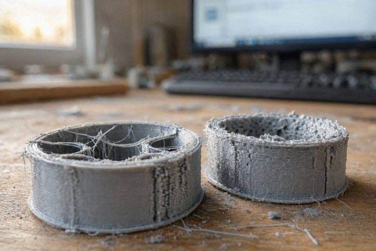
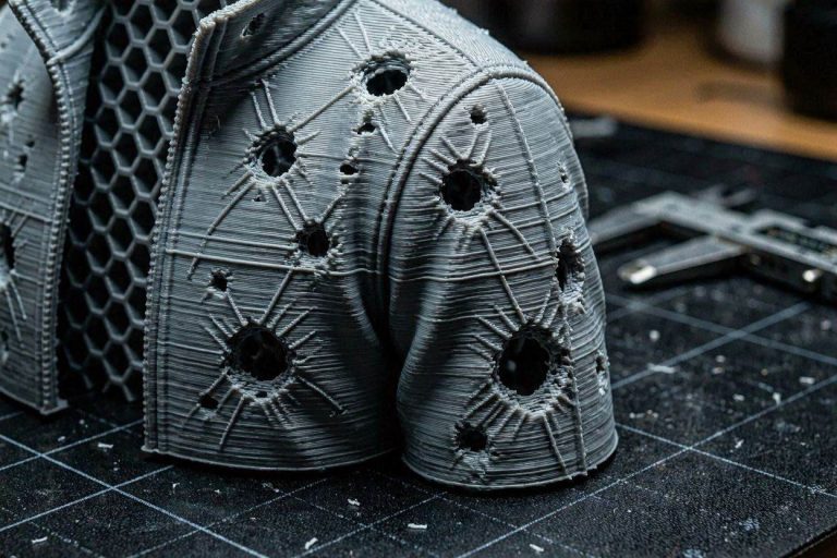
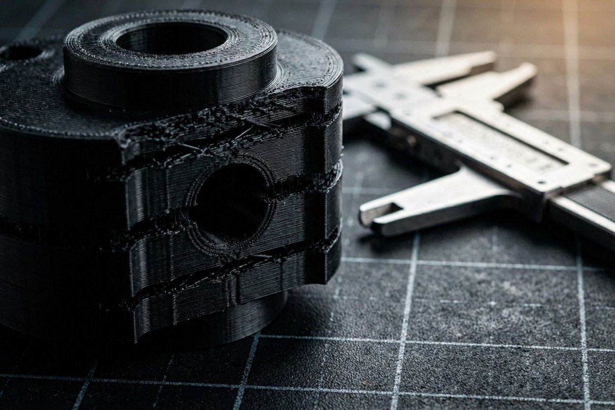
The main walls look perfect, but immediately following any circular hole, window, or bridged gap, the plastic completely tears. The wall becomes a stringy, under-extruded mess for several centimeters before miraculously recovering. If you are desperately searching the forums for a way to fix PETG under-extrusion after holes, you have likely been told to endlessly adjust your temperatures or Z-offsets.
These superficial band-aids will not solve your problem. This specific defect is not a temperature issue; it is a catastrophic failure of kinematic fluid dynamics. In this deeply technical diagnostic manual, we will deconstruct the exact acceleration physics causing your nozzle to starve. By mastering Pressure Advance algorithms and Volumetric Flow throttling, you will possess the exact engineering workflows required to permanently fix PETG under-extrusion after holes and restore your machine to injection-molded tolerances.
The “Quick Answer” / Key Takeaways Box
- The Root Cause: Severe under-extrusion after a hole is caused by a massive acceleration spike. The toolhead slows down to print the hole’s bridge, then instantly accelerates back to maximum speed, starving the nozzle of plastic.
- Pressure Advance Failure: If your Pressure Advance (K-value) is incorrect, the extruder motor fails to pre-pressurize the melt zone before this massive acceleration spike.
- LiDAR Limitations: Auto Flow Dynamics (LiDAR) frequently fails to read black or shiny PETG accurately, resulting in corrupted Pressure Advance data. You must calibrate manually.
- The Volumetric Speed Trap: Printing PETG at 600 mm/s requires an impossible Volumetric Flow Rate. You must hard-cap your Max Volumetric Speed (MVS) to 12-15 mm³/s to prevent pressure drop-offs.
- Avoid Temperature Band-Aids: Dropping your hotend temperature simply masks the issue by altering the cooling dynamics. It sacrifices ultimate layer adhesion and structural part strength.
The Kinematics of Hole Bridging
To successfully fix PETG under-extrusion after holes, you must first visualize the exact kinematic toolpath your printer is executing. A 3D printer does not travel at a constant velocity. It is constantly accelerating, decelerating, and braking based on the geometry it encounters.
When your high-speed printer is laying down a long, straight outer wall, it easily reaches its commanded top speed (e.g., 300 to 600 mm/s). However, when the nozzle approaches a circular hole, the slicing software detects an overhang or a bridge.
To prevent the plastic from sagging into thin air, the slicer commands an emergency brake. The toolhead rapidly decelerates down to 30 mm/s or 50 mm/s to carefully draw the perimeter of the hole.
The Acceleration Starvation Event
The defect occurs the exact millisecond the nozzle finishes printing the perimeter of the hole. The slicer immediately commands the toolhead to return to its maximum outer wall speed.
The lightweight carbon-fiber toolhead accelerates from 30 mm/s back to 300+ mm/s almost instantaneously. The extruder gear spins wildly to keep up. However, PETG is an incredibly viscous, sticky polymer. It cannot react to this sudden geometric demand instantly.
The molten plastic lags behind the mechanical movements of the stepper motors. The nozzle flies across the build area, but the plastic is not ready to flow. The result is a nozzle that prints “empty air” for several centimeters. This creates the exact torn, pitted scarring you are trying to eliminate. To fix PETG under-extrusion after holes, we must force the software to anticipate this lag.
[IMAGE PLACEHOLDER: A technical diagram illustrating the velocity of a 3D printer toolhead as it approaches a hole, decelerates, and rapidly accelerates, causing a drop in nozzle pressure + Alt Text: An engineering diagram explaining the kinematic velocity changes that require you to fix PETG under-extrusion after holes.]
Step 1: Manual Pressure Advance (Linear Advance) Calibration
The primary algorithmic defense against acceleration starvation is Pressure Advance (PA), known as Linear Advance in Marlin firmware. PA calculates the viscosity of the filament and commands the extruder motor to push extra plastic slightly before an acceleration spike.
This pre-pressurizes the nozzle, ensuring that when the toolhead floors the accelerator after a hole, the molten PETG is already surging out of the tip. If you are experiencing gaps, your PA value is mathematically incorrect.
Why Auto-Calibration Fails on Black PETG
Modern high-end machines feature LiDAR sensors to automatically calculate Pressure Advance. The printer lays down a series of test lines, scans them with a laser, and selects the best line.
However, LiDAR is an optical technology. If you are printing with black, glossy, or transparent PETG, the shiny surface scatters the laser light. The sensor cannot accurately read the microscopic width of the extrusion line. It guesses the value, frequently applying a PA number that is drastically too low.
You cannot rely on automation to fix PETG under-extrusion after holes when using difficult finishes. You must override the automation and perform a manual calibration.
Step 2: Executing the OrcaSlicer PA Pattern Test
To find your exact, mathematically perfect K-value, you must transition to a pro-grade slicing environment like OrcaSlicer, which offers deeply integrated calibration tools.
- Open OrcaSlicer and select your specific PETG filament profile.
- Navigate to the top menu bar and select Calibration > Pressure Advance > Pattern Method.
- Set your specific nozzle size (e.g., 0.4mm).
- Run the test print. The machine will print a series of angled lines with varying PA values assigned to each line.
Examine the printed lines under a harsh, directional light. You are looking for the one single line where the sharp corner is perfectly uniform.
- If the line is broken or torn at the acceleration point, the PA value is too low.
- If the line is bulging and bloated at the deceleration point, the PA value is too high.
Find the perfect line, read the corresponding number printed next to it (e.g., 0.045), and hardcode this exact value into your Filament Settings under “Enable Pressure Advance.”
Step 3: Throttling Max Volumetric Speed (MVS)
If your Pressure Advance is perfectly calibrated but the tearing persists, you have run into a hard thermodynamic wall. You are simply asking the hotend to melt plastic faster than the laws of physics allow.
The user in the diagnostic scenario noted they were commanding the printer to run at 600 mm/s. This speed is a marketing metric, not a practical engineering reality for standard filaments.
The Volumetric Flow Equation
Volumetric Flow Rate (VFR) is the absolute measurement of how many cubic millimeters of plastic the hotend is melting per second. The formula is: Line Width × Layer Height × Print Speed = MVS.
If you are printing a standard 0.42mm line width at a 0.2mm layer height at 600 mm/s, the formula is: 0.42 × 0.2 × 600 = 50.4 mm³/s.
A standard ceramic or brass hotend can only successfully melt PETG at a rate of 12 to 15 mm³/s. By commanding the printer to move at 600 mm/s, you are demanding 50.4 mm³/s. The hotend is completely overwhelmed. It cannot melt the cold filament fast enough, resulting in massive, catastrophic under-extrusion the moment the toolhead speeds up after a hole.
To permanently fix PETG under-extrusion after holes, you must open your Filament Settings and locate the Max Volumetric Speed parameter. Change this value to 13 mm³/s. This acts as a global safety governor. The slicer will automatically throttle the toolhead speeds to ensure the extrusion system is never pushed beyond its thermal capacity.
[INTERNAL LINK: Placeholder for “How to Calibrate Max Volumetric Speed for High-Flow 3D Printing Filaments”]
Step 4: Modulating Bridge and Overhang Acceleration Deltas
Even with proper MVS limits, the shock of transitioning from a slow bridge to a fast wall can disrupt the flow of viscous PETG. We must smooth out this kinematic transition.
When the toolhead finishes the slow perimeter of the hole, we do not want it to instantly snap back to full speed. We want it to ramp up gradually, giving the extruder gears time to build internal nozzle pressure.
Navigate to the Speed tab in your slicer settings. Locate the Acceleration parameters. You must lower the Normal Acceleration and Outer Wall Acceleration from their default maximums (often 5000+ mm/s²) down to a more manageable 2000 mm/s² or 2500 mm/s².
By reducing the aggressive “jerk” of the toolhead, the molten polymer has time to catch up with the mechanical movement, laying down a perfectly solid line immediately after leaving the hole geometry.
Step 5: Adjusting Wall Transitions and Ordering
The sequence in which your slicer prints the various components of a wall heavily impacts the final aesthetic quality. If your slicer prints the outer wall first, any pressure anomalies occurring after a hole are immediately visible on the exterior of your model.
To successfully fix PETG under-extrusion after holes, we can manipulate the slicer to hide these pressure drops inside the structural infill of the part.
- Navigate to the Quality tab in your slicer.
- Locate the Wall Ordering (or Wall Printing Order) parameter.
- Change the setting from “Outer/Inner” to Inner/Outer/Infill.
By forcing the printer to complete the internal structural walls first, the toolhead executes the massive acceleration spikes hidden inside the model. If the nozzle starves for a fraction of a second, it leaves a gap on an invisible inner perimeter. By the time it moves to the final outer wall, the nozzle pressure has completely stabilized, resulting in a flawless exterior finish.
Step 6: Why Dropping Temperature is a Dangerous Band-Aid
In the original diagnostic scenario, the user claimed they “solved” the issue by reducing the hotend temperature from 250°C down to 235°C, dropping the flow by 2%, and increasing the Z-offset.
As a professional operator, you must recognize why this is a dangerous illusion.
Lowering the temperature to 235°C increases the viscosity of the PETG. It makes the plastic thicker. Thicker plastic creates more back-pressure inside the nozzle. This artificial back-pressure temporarily masked the fact that their Pressure Advance and Volumetric Speeds were wildly out of calibration.
While the wall may look slightly better visually, printing PETG at 235°C at high speeds drastically reduces layer adhesion. The structural integrity of the part is severely compromised. It will shatter under mechanical stress. You must keep your temperature high (245°C – 255°C) to ensure chemical bonding, and use algorithmic PA tuning to control the flow.
Step 7: Eradicating the Hygroscopic “Popcorning” Effect
PETG is heavily hygroscopic. It absorbs ambient atmospheric moisture incredibly fast. Even if the user claims their AMS unit reads 18% humidity, the filament itself may have absorbed water during the manufacturing or shipping process before it was ever unsealed.
When moisture-laden PETG enters a 250°C hotend, the water instantly flashes into steam. This steam expands violently, creating microscopic explosions inside the melt zone (often referred to as “popcorning”).
These steam pockets physically displace the molten plastic. If a steam bubble bursts exactly as the nozzle is accelerating away from a hole, it completely shatters the extrusion line, leaving a massive gap.
You must treat active desiccation as a mandatory step. Place the spool in a heated filament dryer at 65°C for a minimum of 12 hours. Passive silica gel inside an AMS unit cannot draw deeply embedded moisture out of the polymer core. Bone-dry filament is an absolute prerequisite to fix PETG under-extrusion after holes.
Step 8: The Permanent Fix: Kinematic Upgrades
While algorithmic slicer tuning will drastically improve your dimensional yield, pushing viscous polymers like PETG at high speeds eventually exposes the limitations of stock thermodynamic hardware. Standard brass or stainless steel nozzles simply cannot transfer heat fast enough to maintain consistent pressure during severe acceleration spikes.
To achieve industrial-grade reliability and permanently lock in your extrusion consistency, you must fortify your physical assets.
1. Upgrade to a High-Flow CHT Hotend
When pushing PETG at volumetric limits, the core of the 1.75mm strand often remains semi-solid inside a standard nozzle. This creates massive flow resistance. You must upgrade your hotend architecture to a premium CHT (Core Heating Technology) nozzle.
CHT nozzles feature internal copper splitters that divide the cold filament into three separate flow paths inside the melt zone. This exponentially increases the heated surface area, ensuring the plastic liquefies instantly. By sourcing elite aftermarket hotend upgrades from authorized industrial suppliers via the ShareASale or MatterHackers affiliate networks, you eliminate internal back-pressure. Your machine will recover from bridging decelerations instantly, pouring flawless plastic the second it accelerates.
2. Implement Active Filament Desiccation Ecosystems
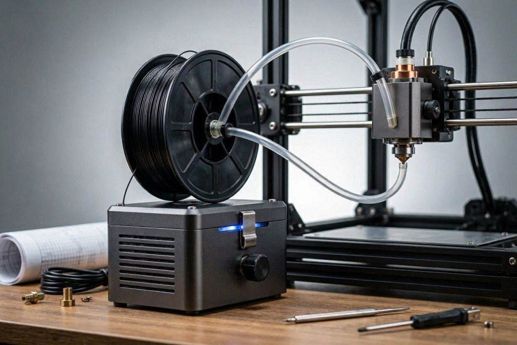
Because PETG is hyper-sensitive to moisture, you cannot rely on cheap plastic tubs. You must invest in a premium, active, heated filament desiccation system like the Sunlu S4.
These units allow you to actively bake the moisture out of four spools simultaneously at 70°C. More importantly, they are designed to feed the bone-dry filament directly from the heated chamber straight into your extruder via sealed PTFE tubing. Sourcing an industrial-grade dry box through direct manufacturer portals on Impact guarantees your polymer never touches humid room air, permanently securing your flow rate dynamics.
Step 9: Quick-Action Preventative Maintenance Checklist
To maintain your flawlessly smooth walls and protect your hardware calibration, implement this strict preventative maintenance protocol before printing complex PETG geometries:
- Audit Extruder Gear Knurling: PETG is tough. If your extruder tension is too high, the hardened steel gears will grind plastic dust off the filament during rapid micro-retractions around holes. Use a stiff brass brush to clean the gear teeth every 100 hours of printing to prevent mechanical slippage.
- Verify PTFE Tube Tolerances: High-speed travel moves cause the filament to slam back and forth inside the reverse-Bowden tubes. If your PTFE tubing is worn or oversized, the filament will buckle, introducing massive latency into your Pressure Advance timing. Upgrade to Capricorn high-tolerance tubing.
- Run Slicer Speed Previews: Before exporting any G-code, navigate to your slicer preview tab and change the color scheme to “Speed.” Visually inspect the areas around holes. If you see the color shift violently from dark blue (slow) to bright red (fast) with no gradient, you need to further lower your acceleration parameters.
- Perform a Nylon Cold Pull: Pushing PETG to its thermal limits often leaves carbonized residue inside the heat break. A partial clog alters nozzle pressure dramatically. Run a cold pull weekly to extract burnt debris and maintain absolute flow purity.
By treating your 3D printer as a highly sensitive fluid dynamics system and refusing to rely on simple temperature band-aids, you will completely eradicate frustrating horizontal tearing. Lock down your Volumetric Flow limits, manually calibrate your Pressure Advance, and start manufacturing complex PETG parts with elite, industrial-grade perfection.