7 Powerful Fixes for a 3D Print Internal Groove Support Nightmare in 2026
If you are dealing with a 3D print internal groove support that is permanently fused to your model, you are encountering a fundamental limitation of Fused Deposition Modeling (FDM). When printing a cylindrical object with a deep, horizontal recess (like an O-ring groove or a pulley channel) in a flat orientation, the slicer is forced to generate an immense amount of support material trapped between two solid walls. When using high-adhesion materials like PLA+ on an Elegoo Carbon, or planning a transition to high-temperature ABS, this trapped material often bonds completely to the main body.
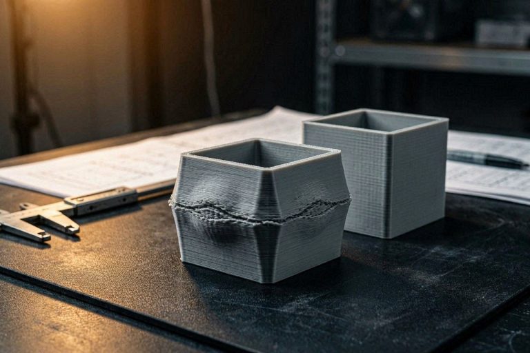
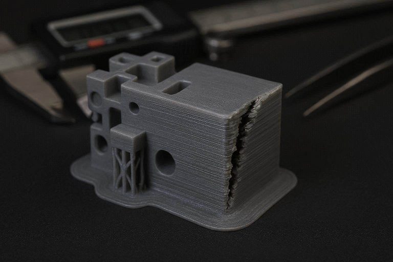
The symptoms are intensely frustrating: you cannot mechanically pry the support out without shattering the main part, and whatever material you do manage to scrape away leaves the internal faces of the groove incredibly rough and dimensionally inaccurate. Diagnosing a fused 3D print internal groove support requires looking beyond default slicer algorithms and rethinking how the digital geometry interacts with physical manufacturing constraints.
This comprehensive, highly technical diagnostic guide will walk you through the exact design, slicing, and hardware adjustments required to conquer trapped overhangs. By implementing these 7 specific steps, you will permanently eliminate your 3D print internal groove support issues and achieve flawless, functional channels.
The “Quick Answer” / Key Takeaways Box
- Step 1: Split the Model (The Ultimate Fix): The most effective mechanical solution is slicing the CAD model in half horizontally along the groove, printing two flat pieces, and assembling them post-print.
- Step 2: Reorient the Print Kinematics: Printing the cylinder vertically or at a 45-degree angle completely changes how the slicer calculates overhangs, often eliminating the need for dense internal supports.
- Step 3: Modify the Groove Geometry: If assembly is not possible, alter the CAD file. Chamfering the upper edge of the groove to a 45-degree angle makes the overhang self-supporting.
- Step 4: Custom CAD Supports: Generate custom, easily removable support blocks equipped with leverage handles directly within your CAD software (like FreeCAD or Fusion360).
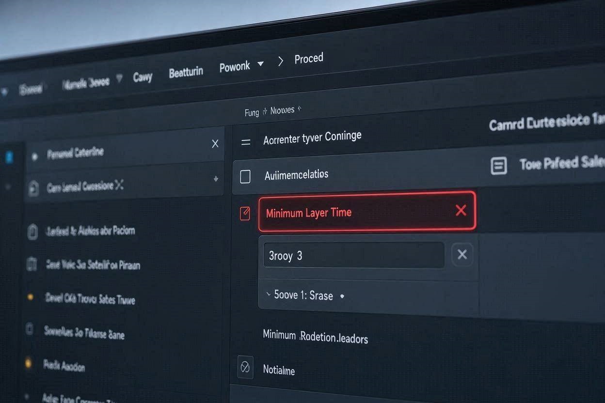
- Step 5: Increase Support Z-Distance: If slicer supports are mandatory, increase the vertical gap (Z-distance) between the top of the support interface and the bottom of the overhang to at least 0.2mm.
- Step 6: Maximize Interface Cooling: Blast the support interface layers with 100% part cooling to ensure the plastic solidifies instantly, preventing it from fusing with the main model.
- Step 7: The Premium Upgrade (Dual Extrusion): Transition to a multi-material system and utilize water-soluble PVA/PVOH filament for the support interface, ensuring a mathematically perfect surface finish.
Understanding the Physics of a Trapped Overhang
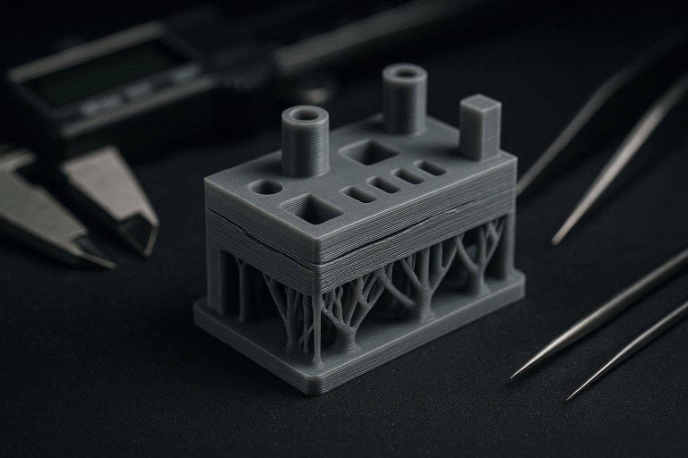
To successfully troubleshoot a stubborn 3D print internal groove support, we must first examine the physical reality of what the toolhead is executing. When your Elegoo Carbon encounters a 90-degree overhang inside a narrow channel, it cannot deposit molten plastic in mid-air. The slicer generates a scaffold of support material beneath the overhang to provide a physical foundation.
The critical failure point occurs at the “interface layer”—the exact microscopic boundary where the disposable support material touches the permanent model. Because you are printing the main body and the support structure out of the exact same PLA+ filament, the two materials want to naturally fuse together under the intense 210°C+ thermal energy.
When this interface layer is buried deep inside a narrow groove, the ambient heat gets trapped. This localized heat accumulation prevents the interface layer from cooling rapidly, causing the support scaffold and the main overhang to melt into a single, unified block of plastic. This thermal fusion is the primary physical catalyst for a 3D print internal groove support that is impossible to remove.
The Problem With 90-Degree Internal Channels
A common misconception in digital fabrication is that slicers can magically optimize any CAD geometry for FDM printing. If you design a part intended for CNC lathe machining (which easily cuts deep grooves) and send it directly to a 3D printer, you are ignoring the rules of additive manufacturing. Items must always be designed for their specific production method.
A 90-degree horizontal groove printed flat on the bed is the absolute worst-case scenario for FDM. The upper lip of the groove is entirely unsupported, and the support material generated beneath it is physically trapped by the lower lip of the groove and the inner wall of the cylinder.
When you attempt to mechanically remove this trapped 3D print internal groove support using pliers or a screwdriver, you lack the physical leverage required to break the fused interface layer. You end up gouging the plastic, leaving a rough, jagged surface that is functionally useless for housing an O-ring or bearing.
The 7-Step Resolution for Internal Groove Supports
Resolving a chronic 3D print internal groove support issue requires taking systematic control of your CAD design, print orientation, and slicer kinematics. We cannot rely on automated support generation to fix deep-rooted geometric incompatibilities. You must actively rewrite the physical boundaries that govern your machine’s operation.
We will adjust the exact sequence of how the model is oriented, how the support interfaces are calculated, and how the hardware executes the deposition. By optimizing these specific actions, you will stabilize the overhangs and achieve flawless internal finishes.
Open your preferred CAD software and your slicer interface (such as OrcaSlicer or Elegoo Cura) and prepare to override your default parameters. Follow these seven highly technical steps to permanently conquer trapped supports.
Step 1: Split the Model (The Ultimate Mechanical Fix)
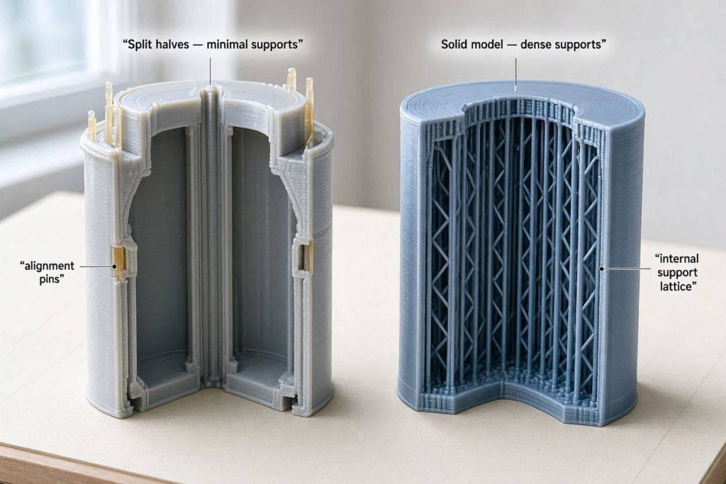
The absolute most reliable, professional, and elegant solution to an impossible 3D print internal groove support is to eliminate the need for supports entirely. As noted in the successful community updates, the definitive fix is splitting the digital CAD model in half horizontally, right through the center axis of the groove.
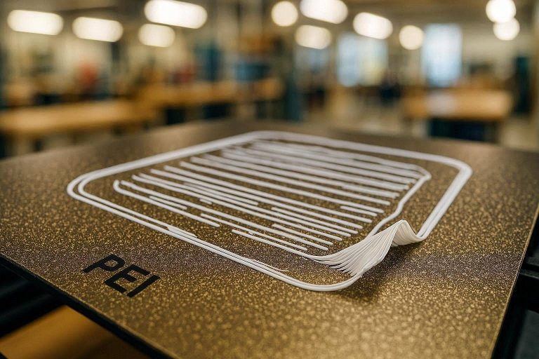
By cutting the cylinder into two separate halves, you completely eliminate the 90-degree overhangs. You now have two distinct pieces, both of which feature a perfectly flat bottom surface. You can lay both flat faces directly against your PEI build plate.
The printer will effortlessly execute the geometries without generating a single drop of support material. The resulting internal faces of the groove will be mathematically perfect, reflecting the smooth texture of your build plate. After the print finishes, you simply align the two halves and bond them together using CA glue (Cyanoacrylate), epoxy, or by designing interlocking alignment pegs directly into the CAD file.
Step 2: Reorient the Print Kinematics
If mechanically splitting the model is not structurally viable for your final ABS application, your next most powerful weapon is print orientation. Printing a cylindrical groove with the flat face down forces the slicer to combat a severe 90-degree horizontal overhang.
You must physically rotate the model within your slicer software to change how gravity and the toolhead interact with the geometry. Reorienting the cylinder to print perfectly vertically (standing it up on its curved edge) changes the 90-degree overhang into a continuous curve. While this requires a small brim to maintain bed adhesion, it often completely eliminates the need for dense internal scaffolds.
Alternatively, pitch the entire model backward at a 45-degree angle. By angling the cylinder, the upper lip of the groove becomes a self-supporting 45-degree slope. Modern FDM printers like the Elegoo Carbon can flawlessly bridge a 45-degree incline without requiring any 3D print internal groove support beneath it, resulting in a remarkably clean channel finish.
Step 3: Modify the Groove Geometry (Chamfering)
When operating within the constraints of Fused Deposition Modeling, you must adhere to the “45-Degree Rule.” If an overhang exceeds 45 degrees from the vertical axis, gravity will begin to pull the molten plastic downward before it can cool.
A standard, square O-ring groove violates this rule entirely. If the functional requirements of your part allow for geometric flexibility, you must return to your CAD workspace (such as FreeCAD) and modify the channel profile.
Instead of a harsh 90-degree upper lip, apply a heavy chamfer (an angled cut) to the top edge of the groove. By sloping the ceiling of the channel at a 45-degree angle, you provide a stepped foundation for the subsequent layers. The nozzle can gracefully step out into space, building upon the previous layer without requiring a messy 3D print internal groove support scaffold underneath.
Step 4: Engineer Custom CAD Supports
Relying on a slicer’s automated algorithm to generate a 3D print internal groove support often results in a densely packed, inaccessible plastic brick. To regain absolute control over the removal process, you can manually engineer custom breakaway supports directly within your native CAD environment.
Open your FreeCAD file and design a secondary, independent body that fits snugly inside the groove. This custom support block should be modeled with a microscopic 0.15mm tolerance gap between its outer walls and the groove’s inner walls.
Crucially, design robust “handles” or pull-tabs that extend outward from the custom support block, protruding past the exterior wall of the main cylinder. Because you control the exact geometry, you can engineer the support to slide out easily. After the print finishes, you simply grab the integrated handles with heavy pliers and use mechanical leverage to rip the custom scaffold out of the channel in one swift motion.
Step 5: Maximize the Support Z-Distance
If modifying the CAD file or changing the print orientation is strictly prohibited by your engineering parameters, you must force your slicer software to weaken the interface bond. The primary variable controlling this bond is the “Support Z Distance.”
The Support Z Distance defines the microscopic vertical air gap left between the highest layer of the support scaffold and the lowest layer of the actual model overhang. By default, slicers often set this to 0.1mm, which results in severe thermal fusion with high-temperature materials like PLA+ or ABS.
Navigate to the advanced support settings in OrcaSlicer or Cura. You must increase the Support Z Distance to a minimum of 0.2mm, or even 0.25mm. This larger air gap prevents the molten overhang from completely welding to the scaffold below it. While a larger gap may result in very slight drooping on the underside of the overhang, it guarantees that you can physically snap the 3D print internal groove support away with a specialized picking tool.
Step 6: Maximize Interface Cooling Dynamics
As discussed, trapped thermal energy is the primary reason an internal support structure fuses to the main body. When the nozzle travels deep inside a narrow channel, the ambient heat cannot escape, keeping the interface layer dangerously soft.
To combat this, you must aggressively manipulate your printer’s part-cooling fans specifically during the interface generation phase. Blasting the interface layers with cold air forces the plastic to solidify instantly, preventing it from deeply intermingling with the main overhang above it.
Within your slicer’s cooling settings, locate the parameters for support interface cooling. Ensure your fans are commanded to jump to 100% capacity exclusively when printing the dense interface roof. This rapid shock-cooling creates a brittle, weak boundary layer that makes removing a stubborn 3D print internal groove support significantly easier.
Step 7: The Premium Upgrade (Multi-Material Support)
Sometimes, endless software tweaking and geometric compromises are not acceptable for highly precise engineering prototypes. If you demand a mathematically perfect, glass-smooth internal groove finish on complex ABS parts, you must look beyond single-extruder hardware limitations.
The ultimate, permanent fix for a destructive 3D print internal groove support is transitioning to a premium multi-material ecosystem, such as the Bambu Lab AMS or a Prusa XL dual-toolhead system. These high-ticket upgrades allow you to print the main body out of rigid ABS or PLA+, while printing the dense interface layers out of a completely different, specialized support filament.
Utilize water-soluble PVA (Polyvinyl Alcohol) or PVOH as your dedicated support interface material. The printer automatically swaps filaments, laying down a foundation of PVA exactly where the overhang occurs. After the print finishes, you simply drop the entire model into a bucket of warm water.
Over a few hours, the PVA interface dissolves completely into a liquid, leaving zero mechanical residue. The main part emerges with a flawless, injection-molded quality finish deep inside the groove, completely eliminating the need for pliers, scraping, or destructive post-processing. You can source premium PVA materials through dedicated 3D printing affiliate networks like ShareASale or directly from high-end retailers like MatterHackers.
Preventative Maintenance Checklist for Flawless Overhangs
To ensure your FDM ecosystem remains highly stable and you never experience a catastrophic 3D print internal groove support failure again, integrate these critical checks into your regular machine maintenance workflow before starting any complex prints:
- Dry Your Filament Aggressively: Wet PLA+ or ABS boils inside the hotend, creating steam explosions that cause the extruded plastic to foam and expand. This foamy expansion fills the microscopic Z-distance gaps, permanently welding the supports to the model. Run your spools through an active heated filament dryer for a minimum of 6 hours prior to printing.
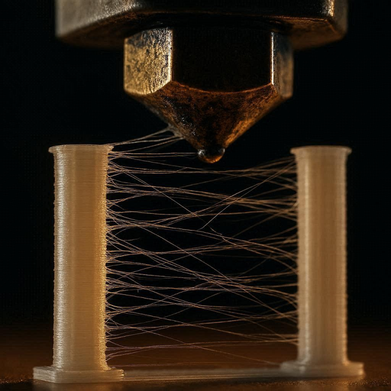
- Calibrate Extrusion Multipliers: If your printer is slightly over-extruding, it will push excess plastic into the support gaps, causing thermal fusion. Run a precise flow-rate calibration cube to ensure your machine is delivering exactly 100% of the requested volume, and not a drop more.
- Invest in Quality Flush Cutters: When dealing with difficult single-material supports, having the right tools is paramount. Upgrade to a set of premium, hardened-steel flush cutters and a specialized dental pick set. These tools allow you to apply targeted, precise mechanical leverage to snap away interface layers without gouging the internal groove walls.