7 Proven Ways to Fix FDM Wall Gaps and Stuck Supports (Stop Print Failures!)
Making the transition back to Fused Deposition Modeling (FDM) after spending years in the resin printing ecosystem can be a jarring mechanical shock. Resin printing is fundamentally a photochemical process; if your exposure times are correct, the print generally succeeds. FDM, on the other hand, is a highly complex thermodynamic and kinematic balancing act. If you are struggling with poor layer adhesion and trying to fix FDM wall gaps and stuck supports, you are battling fluid dynamics, not just software settings.
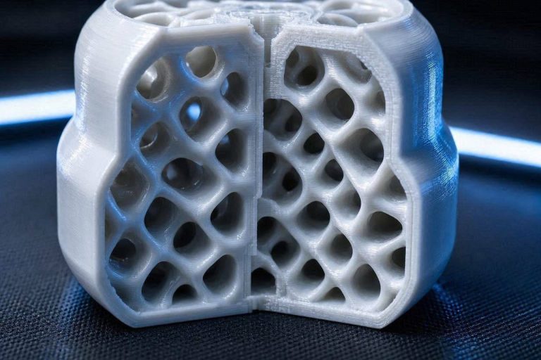
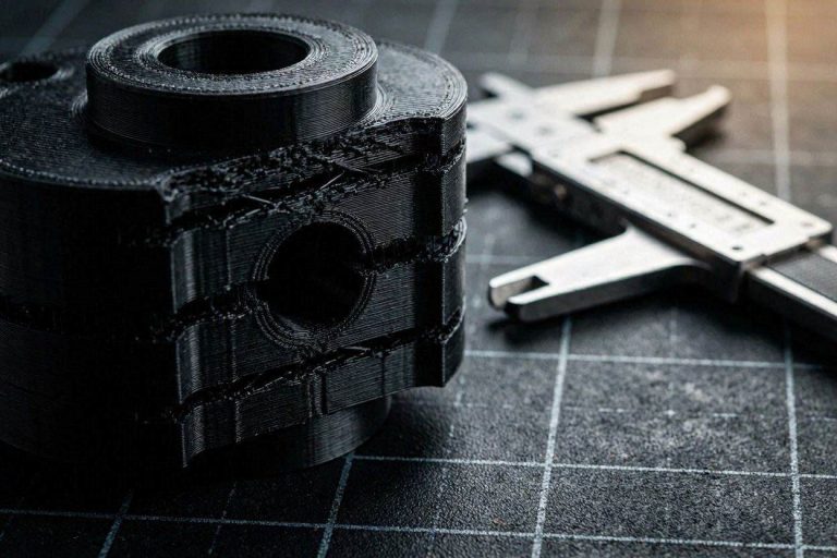
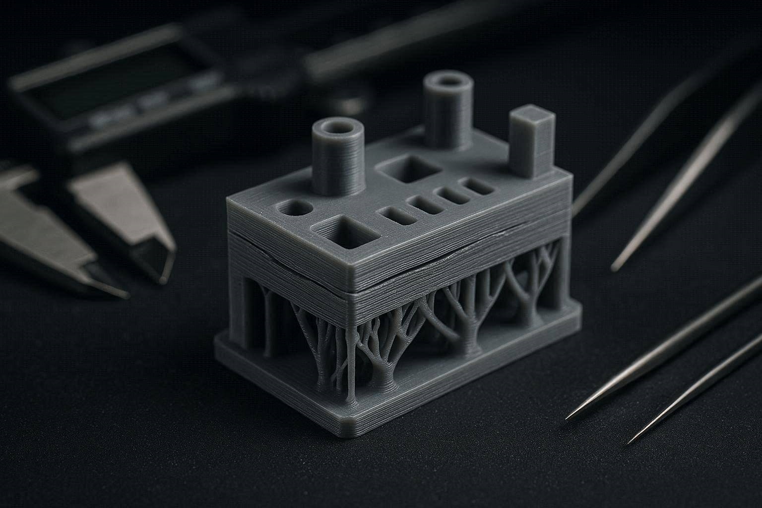
Many returning operators fire up their older machines, like a first-generation Wanhao D12-300, install a modern slicing engine like OrcaSlicer, and are immediately met with frustrating artifacts. You might see outer perimeters completely failing to bond with the internal infill structure. You may also find that your organic tree supports have chemically welded themselves to your model, requiring destructive force to remove.
In this exhaustive, deeply technical diagnostic manual, we will deconstruct the exact physics occurring at the tip of your 0.4mm nozzle. We will analyze the volumetric flow failures causing your perimeters to separate and the thermal bridging errors causing your supports to fuse. By executing these specific engineering workflows, you will permanently fix FDM wall gaps and stuck supports, restoring your machine to injection-molded tolerances.
The “Quick Answer” / Key Takeaways Box
- The First Layer Trap: Setting your first layer height to 0.4mm on a 0.4mm nozzle is physically impossible to extrude properly. It destroys the “squish” required for bed adhesion and volumetric pressure.
- Volumetric Under-Extrusion: Gaps between your outer walls and infill are the primary symptom of a flow rate deficiency. You must calibrate your Extrusion Multiplier specifically for your spool of PLA.
- The Support Fusion Failure: If supports are impossible to remove, your Z-distance is either mathematically incorrect for your layer height, or you are over-extruding plastic on the support interface layer.
- Infill-to-Wall Overlap: While a 25% overlap is mathematically sound, it completely fails to bridge the gap if the inner wall is suffering from kinematic under-extrusion.
- Arachne Engine Tuning: Small top surface gaps and missing text details are caused by uncalibrated minimum feature size thresholds within modern variable-line-width slicer engines.
The Physics of Extrusion: Why You Must Fix FDM Wall Gaps and Stuck Supports
Before adjusting a single slider in OrcaSlicer, you must understand the fluid dynamics occurring inside your hotend. FDM printing relies on a concept known as “die swell” and volumetric pressure. When solid PLA filament is pushed into a 205°C melt zone, it liquefies. The extruder motor forces this liquid through a microscopic 0.4mm orifice.
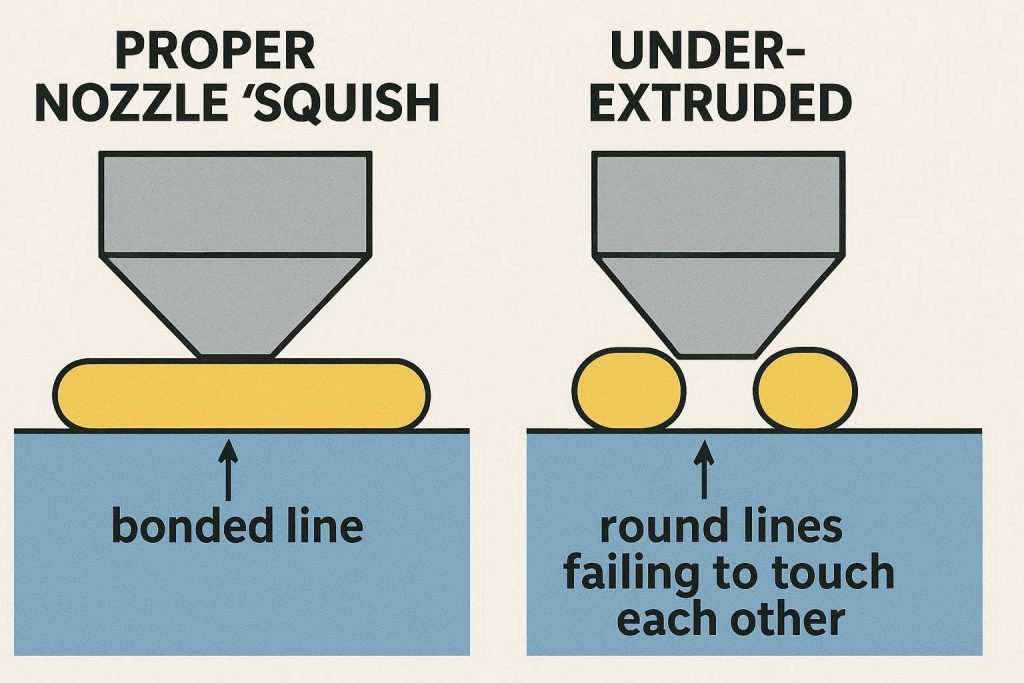
To create a strong, solid part, the printer does not just lay down a perfectly round tube of plastic. It relies on the flat geometry of the nozzle tip to physically “squish” the molten polymer against the previous layer. This squish forces the plastic to expand horizontally, fusing with the adjacent lines of plastic.
If this internal nozzle pressure drops—even by a microscopic 2% or 3%—the plastic is laid down as a thin, stretched string rather than a squished, widened ribbon. When the plastic is too thin, the line assigned to the “Outer Wall” will physically fail to touch the line assigned to the “Infill.” This creates the exact visual gaps you are experiencing. To properly fix FDM wall gaps and stuck supports, we must mathematically guarantee that your hotend is maintaining absolute maximum volumetric pressure.
Step 1: Correcting the First Layer Height Ratio
The most glaring kinematic error in your current slicing configuration lies within your fundamental layer geometry. You are utilizing a standard 0.4mm brass nozzle. However, your slicer profile dictates a standard layer height of 0.2mm, with a First Layer Height of 0.4mm.
This is a catastrophic geometric impossibility in additive manufacturing.
The Flat-Tip Geometry Limit
A 3D printer nozzle is not a hypodermic needle. It features a flat brass shoulder surrounding the 0.4mm hole. This flat shoulder is what irons the plastic flat. As a universal law of FDM physics, your absolute maximum layer height can never exceed 80% of your physical nozzle diameter.
If you attempt to print a 0.4mm high layer out of a 0.4mm nozzle, the nozzle is floating exactly at the maximum diameter of the extrusion. The plastic drops out of the tip as a perfectly round cylinder. There is zero downward mechanical pressure applied to the polymer. It will not squish into the textured build plate, and the adjacent lines will not fuse together.
The Fix: You must navigate to your Quality tab in OrcaSlicer.
- Change your First Layer Height from 0.4mm to 0.2mm or 0.24mm.
- By lowering the nozzle closer to the bed, the extruder forces the plastic to spread out horizontally. This secures absolute bed adhesion and establishes the high-pressure volumetric baseline required for the rest of the print.
Step 2: Calibrating Flow Dynamics to Fix FDM Wall Gaps and Stuck Supports
Once your foundational first layer is mathematically viable, we must address the severe separation visible between your outer perimeters and your internal geometry. While it is tempting to blame the infill overlap percentage, the primary culprit for this separation is global under-extrusion.
You are printing with a budget-tier PLA. Inexpensive filaments frequently suffer from dimensional inaccuracy. While the spool claims the filament is 1.75mm thick, digital calipers will often reveal it is actually 1.71mm or 1.72mm thick.
The Volumetric Deficit
Your slicer assumes the filament is exactly 1.75mm. It calculates the extruder motor steps based on that absolute volume. If the filament is thinner, the extruder is pushing significantly less total volume of plastic into the melt zone. The pressure drops, the lines become microscopically thinner, and the outer walls physically detach from the infill structure.
To permanently fix FDM wall gaps and stuck supports related to dimensional variance, you must execute a strict flow rate calibration.
The Fix:
- Open OrcaSlicer and navigate to the top menu bar. Select Calibration > Flow Rate > Pass 1.
- Print the generated test blocks.
- Examine the top surface of the blocks under a harsh directional light. You are looking for the block that is perfectly smooth. If your current prints have gaps, your optimal block will likely be a positive value (e.g., +5).
- Input the corresponding mathematical formula into your Filament Settings under the Flow Ratio parameter. Increasing your flow from the default 1.00 up to 1.03 or 1.05 will instantly expand your extrusion lines, forcing the outer walls to permanently chemically weld to the infill.
[INTERNAL LINK: Placeholder for “How to Calibrate Max Volumetric Speed for High-Flow 3D Printing Filaments”]
Step 3: Optimizing Infill to Wall Overlap Settings
If your flow rate is perfectly calibrated but a microscopic separation still exists on highly complex curves, we must intervene in the specific kinematic pathing of the slicer.
In your OrcaSlicer Strength tab, your Infill/wall overlap is configured to 25%. This setting instructs the toolhead to push the infill lines 25% of the way into the inner wall perimeter line. Under perfect mathematical conditions, 25% is an excellent standard setting. However, on older mechanical hardware, mechanical backlash can cause the toolhead to fall slightly short of its target coordinate.
Compensating for Mechanical Backlash
Older machines utilizing standard V-slot wheels and early-generation stepper drivers often exhibit a fraction of a millimeter of physical “slop” when rapidly changing directions from a perimeter sweep to an infill zig-zag.
The Fix: To brutally override this mechanical slack and definitively fix FDM wall gaps and stuck supports, you must aggressively increase the physical overlap limit.
- Increase your Infill/wall overlap from 25% up to 35% or even 40%.
- This forces the nozzle to physically plow deeper into the perimeter wall.
- Simultaneously, ensure your Walls printing order is set to Inner/Outer. This ensures the infill anchors itself deeply into the inner wall first, before the final, aesthetically critical outer wall is laid down to hide the messy internal connection.
Step 4: Mastering Z-Distance for Easy Support Removal
The second major crisis in your diagnostic request involves your support structures. When organic tree supports are functioning correctly, they should snap away from the model with a satisfying crunch, leaving almost zero scarring behind. If you feel like you are going to break your model while removing supports, your support interface has chemically welded itself to the part.
To fix FDM wall gaps and stuck supports, you must understand how slicing software manages air gaps. Support structures are not meant to touch the model; they are meant to float fractionally below it.
The Z-Distance Equation
In your OrcaSlicer configuration, your Top Z distance is set to 0.2mm. Because your main layer height is also 0.2mm, you are leaving exactly one single missing layer of air between the top of the support structure and the bottom of your model.
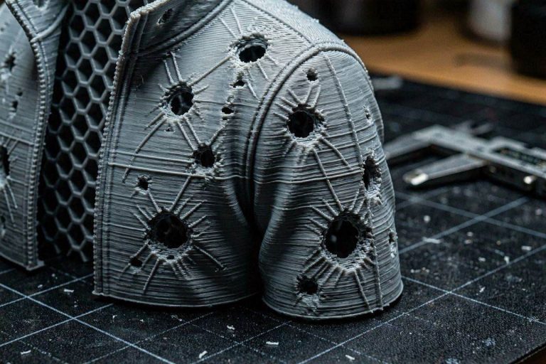
For high-end, perfectly cooled CoreXY machines, a one-layer gap is standard. However, if your printer’s part-cooling fans are weak, or if you are printing slightly too hot (205°C is on the warmer side for some low-grade PLAs), the molten plastic will bridge that 0.2mm air gap and sag downwards. The hot plastic touches the support structure below it and permanently fuses.
The Fix: You must increase the physical separation distance to overcome inadequate part cooling.
- Navigate to your Support tab.
- Increase your Top Z distance from 0.2mm to 0.25mm or 0.28mm.
- This creates a much larger air gap. The filament will still sag enough to rest gently on the support interface, but it will cool down rapidly before it can chemically bond to the structure below it.
Step 5: Interface Spacing and Pattern Density
A larger Z-distance will prevent chemical welding, but if your supports are still physically difficult to remove, your interface pattern is too dense. The “interface” is the specialized, solid roof printed at the very top of the tree support branch, right before the model begins.
If this interface roof is printed as a 100% solid sheet of plastic, it creates massive surface area contact with your model. More surface area equals more mechanical grip, which directly leads to impossible support removal. We must reduce the surface area to effectively fix FDM wall gaps and stuck supports.
Adjusting the Interface Spacing
Looking at your configurations, your Top interface spacing is set to 0.5mm. This means the slicer is laying down lines of plastic with a tiny half-millimeter gap between them. This creates a nearly solid sheet.
The Fix:
- Increase your Top interface spacing significantly, moving from 0.5mm up to 1.0mm or 1.2mm.
- Change your Top interface pattern from “Default” or “Rectilinear” to Concentric.
- This drastically reduces the density of the support roof. The roof becomes a fragile, grid-like mesh rather than a solid plate. It still provides adequate vertical support to prevent the model from failing, but it will crush and tear away effortlessly with a pair of needle-nose pliers.
[VIDEO PLACEHOLDER: A highly detailed macro video demonstrating the ease of removing concentric support interfaces with a 0.25mm Z-distance gap.]
Step 6: Addressing Top Layer Gaps and Small Text Resolution
In your diagnostic photos, the flat top surfaces of the calibration test show visible pitting, and the small text details look jagged and unresolved. While increasing your global flow rate (Step 2) will mitigate much of this, you must also optimize the modern variable-line-width algorithms within OrcaSlicer.
OrcaSlicer utilizes the Arachne wall generator. Unlike classic slicing engines that rely on fixed-width extrusion lines (e.g., exactly 0.4mm everywhere), Arachne dynamically widens and narrows the extrusion flow to perfectly fill gaps and small details.
Fine-Tuning Arachne Parameters
However, if Arachne’s minimum limits are set too aggressively, it will simply refuse to print details that it deems too small for the nozzle.
The Fix: To fully resolve top surface aesthetics and fix FDM wall gaps and stuck supports related to small features, navigate to the Quality tab.
- Ensure your Wall generator is set to Arachne.
- Locate the Minimum feature size parameter. Reduce this from 25% down to 15%. This forces the slicer to attempt to extrude incredibly thin strings of plastic to fill in the jagged edges of small embossed text.
- Enable Small area flow compensation. This advanced feature commands the extruder to inject slight bursts of extra pressure into tiny top-surface gaps, completely eradicating the “chatter” and pitting visible in your calibration photos.
[EXTERNAL LINK: Official PrusaSlicer Documentation on the Kinematics of the Arachne Wall Generator Engine]
Step 7: Filament Dehydration and Thermal Baseline
If you have perfectly calibrated your flow, increased your Z-distances, and tuned your Arachne limits, but your prints still look brittle or your supports refuse to detach cleanly, you have a chemical contamination problem.
Coming from resin printing, you are accustomed to photopolymer resins requiring specific temperature ranges. FDM filaments require strict moisture control. Even brand-new, vacuum-sealed spools of PLA contain residual manufacturing moisture trapped within the polymer matrix.
The Steam Expansion Failure
When moisture-laden PLA hits a 205°C hotend, the trapped water flashes into steam. This steam expands violently inside the nozzle, physically displacing the plastic. This causes microscopic, random gaps in your outer walls and unpredictable blobs on your support interfaces, completely ruining your calibrated clearances.
The Fix: You must treat dehydration as a mandatory pre-production requirement. Do not rely on passive silica gel boxes. Place your Kingroon PLA into an active, heated filament dryer at 45°C for a minimum of 6 hours before attempting to print your calibration towers again. Bone-dry filament flows with absolute volumetric predictability, securing the final step required to permanently fix FDM wall gaps and stuck supports.
The Permanent Fix: High-Quality Kinematic Upgrades
While advanced software calibration is the mandatory first step to restoring your machine, an older first-generation 3D printer possesses severe physical limitations. Software algorithms cannot permanently fix cheap thermal engineering or worn-out PTFE-lined hotends. To achieve absolute, injection-molded surface perfection without spending hours tweaking slicer profiles for every new spool, you must upgrade your foundational hardware ecosystem.
1. Upgrade to a High-Flow CHT Nozzle
Standard brass nozzles feature a single, smooth internal bore. When attempting to push thick polymers at reasonable speeds, the core of the plastic often remains semi-solid, creating massive back-pressure that leads to under-extrusion and separating walls.
You must upgrade your hotend architecture to a premium CHT (Core Heating Technology) nozzle. These advanced components feature internal copper splitters that divide the filament into three separate pathways inside the melt zone. This exponentially increases the heated surface area, ensuring the plastic melts instantly and homogenously. By sourcing a premium CHT nozzle through industrial suppliers via the MatterHackers or ShareASale affiliate networks, you completely eliminate internal hotend pressure drops. Your machine will extrude flawless, high-squish lines that permanently bond to the infill.
2. Implement BMG-Style Dual Drive Extrusion
If your older machine is still utilizing a single-gear extruder pressing against a smooth idler bearing, you will forever battle under-extrusion. Single gears slip easily, especially when executing rapid retractions around support structures.
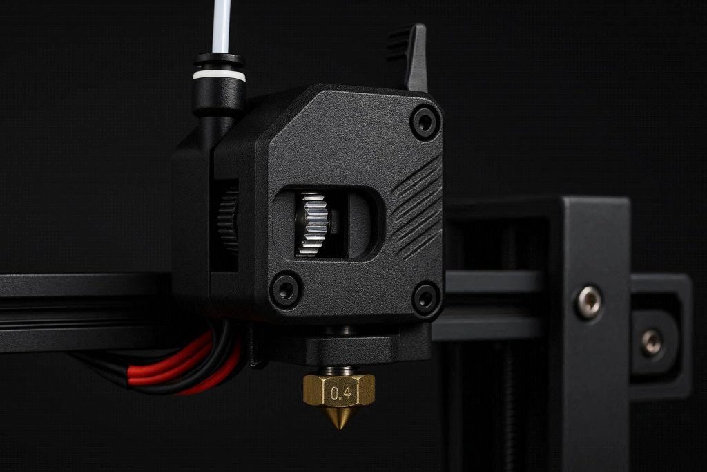
Upgrading your kinematics to a CNC-machined, zero-tolerance dual-drive extruder utilizing the BMG (Bondtech Mini Geared) architecture guarantees absolute flow control. These extruders grip the filament from both sides simultaneously, offering a 3:1 gear reduction ratio for massive torque. You can source elite aftermarket extruders directly through manufacturer partner programs on the Impact network, entirely eliminating the mechanical slippage that causes wall separation.
3. Professional Active Desiccation Hardware
As established, moisture destroys extrusion dynamics. You must invest in a premium, active, heated filament desiccation system like the Sunlu S4. These units allow you to actively bake the moisture out of multiple spools simultaneously at 50°C to 70°C. More importantly, they are designed to feed the bone-dry filament directly from the heated chamber straight into your extruder via sealed PTFE tubing. Securing this hardware ensures your polymer never touches humid room air, permanently locking in your highly sensitive extrusion calibrations.
Quick-Action Preventative Maintenance Checklist
To maintain your flawlessly solid outer walls and effortless support removal, implement this strict preventative maintenance protocol before your next major production run:
- Audit Your First Layer Geometry: Never let your first layer height equal your nozzle diameter. Always keep it between 0.2mm and 0.28mm on a 0.4mm nozzle to ensure maximum volumetric squish.
- Recalibrate Flow Per Spool: Different colors and brands of filament possess different chemical densities. You must run a quick OrcaSlicer flow calibration pass for every single new spool you purchase to prevent wall separation.
- Wipe Down Linear V-Wheels: Older printers use rubber V-wheels riding on aluminum extrusions. Dust turns into a hard, abrasive paste on these wheels, causing micro-stuttering that creates wall gaps. Wipe the wheels and extrusions clean with isopropyl alcohol weekly.
- Perform a Nylon Cold Pull: Running low-grade PLA frequently leaves burnt residue inside the hotend. A partial clog severely drops nozzle pressure. Run a high-tension nylon cold pull every 50 print hours to extract carbonized debris and maintain absolute flow purity.
By treating your FDM printer as a high-precision fluid dynamics system and respecting the severe physical limitations of nozzle geometry, you will completely eliminate frustrating print failures. Stop accepting brittle, separating prints, dial in your flow and support interfaces, and start manufacturing with elite, industrial-grade perfection.