How to Calibrate Max Volumetric Speed for High-Flow Filaments (The Definitive Guide)
In the era of modern, high-acceleration CoreXY 3D printers and deeply optimized Klipper firmware, linear speed metrics like “300 mm/s” have largely become obsolete. Pushing your machine’s motion system to blistering velocities means very little if your hotend cannot maintain thermal equilibrium with the material passing through it. When transitions fail, lines tear, or layers delaminate at high speeds, you aren’t suffering from an inadequate motion chassis—you are running into a hard thermodynamic ceiling. To fix this, you must calibrate max volumetric speed.
Max Volumetric Speed (MVS), measured strictly in cubic millimeters per second ($mm^3/s$), defines the absolute volume of molten polymer your hotend can reliably melt and extrude per second before the internal nozzle pressure overwhelms your extruder motor. High-flow filaments (such as PLA HF, PETG HF, or carbon-fiber filled speed resins) are specially chemically engineered with lower molecular weights or flow-enhancing additives to expand this ceiling. However, every hardware combination possesses a unique thermal bottleneck.
In this comprehensive, highly technical calibration guide, we will break down the exact physics of polymer melting mechanics. We will explore the mathematical relationships between line geometry and print speed, provide a bulletproof step-by-step raw testing protocol using OrcaSlicer, and detail how to integrate your findings directly into your slicing profiles. By the end of this manual, you will be able to maximize your machine’s manufacturing throughput with zero risk of hidden under-extrusion.
The “Quick Answer” / Key Takeaways Box
- The Core Metric: Volumetric Flow Rate (mm^3/s) is the true governor of 3D printing speed. Linear speed (mm/s) is merely a product of your desired layer height, line width, and volumetric capacity.
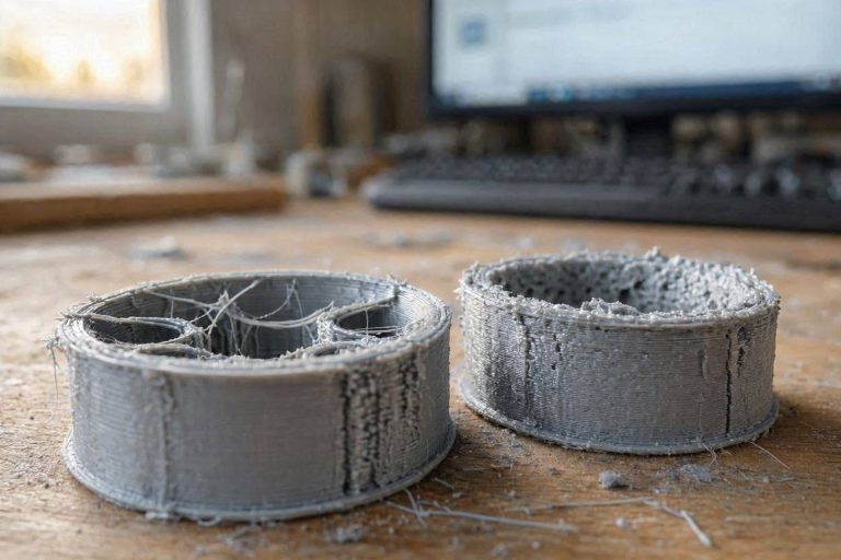
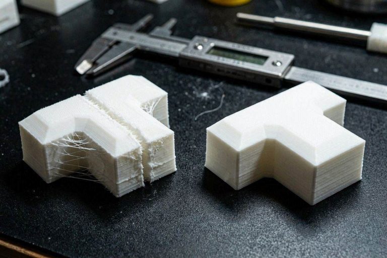
- The Failure Mode: Exceeding your hotend’s maximum volumetric speed causes the core of the filament strand to remain solid. This spikes internal nozzle pressure, causing the extruder gears to slip or click, leading to structural layer delamination and a loss of surface gloss.
- The Test Protocol: Use the Ramp Test (built into OrcaSlicer), which continuously scales the volumetric flow from a baseline of 5mm^3/s up to 40mm^3/s over a vertical column.
- The Calculation: Identify the physical Z-height where the print quality degrades, turns matte, or tears, and apply the formula: VFR + Height *Step to locate your hard ceiling.
- The Safety Margin: Always subtract a 10% safety margin from your absolute failure threshold to account for minor filament diameter variances and thermal ambient fluctuations during long production runs.
The Thermodynamic Physics of Volumetric Flow
To successfully calibrate max volumetric speed, you must first visualize the complex heat transfer occurring inside your machine’s melt zone. A standard 1.75mm filament strand enters the cold zone of the toolhead as a solid, rigid polymer rod. As the extruder motor drives this rod downward, it enters the thermal break and passes into the heater block.
The plastic does not melt instantaneously. Heat must conduct from the outer surface of the filament strand inward toward the center core. This physical process is governed by the polymer’s specific heat capacity and thermal conductivity.
- Sufficient Dwell Time (Low Speed): When printing slowly, the filament spends a prolonged duration inside the heated barrel. The heat thoroughly penetrates the core, turning the entire 1.75mm cross-section into a homogeneous, highly fluid liquid with minimal internal friction.
- Insufficient Dwell Time (High Speed): When you accelerate the print speed without calibrating your volumetric limits, the filament rushes through the heater block too quickly. The outer skin of the plastic melts, but the center core remains a solid, un-melted plastic plug.
This un-melted core physically chokes the nozzle orifice. The direct-drive extruder motor must exert massive downward force to attempt to squash this solid plug through a microscopic 0.4mm opening. Internal nozzle pressure skyrockets.
Eventually, the pressure exceeds the mechanical grip of your extruder gears. The teeth begin to chew through the plastic, or the stepper motor skips micro-steps (manifesting as an audible clicking noise).
At the nozzle tip, the plastic exits unevenly, creating tiny pits, rough matte finishes, or structural tears in the outer walls. To stabilize this system, you must determine exactly where this thermal threshold resides.
The Volumetric Flow Equation
Before running the physical test, you must understand the mathematical framework that modern slicing engines use to control toolhead velocity. The slicer continuously calculates the required Volumetric Flow Rate (VFR) using three physical variables:

Why Linear Speed is a Deceptive Metric
Let us look at how this equation impacts real-world printing dynamics. Assume your hotend has an absolute maximum melting capacity of 15 $mm^3/s$ for a standard brand of PLA.
- If you slice a model with a 0.2mm layer height and a 0.42mm line width, your maximum safe linear speed is:15 / (0.42 x 0.2) = 178.5mm/s
- If you drop your layer height to an ultra-fine 0.08mm while keeping the same 0.42mm width, your maximum safe linear speed leaps to:15 / (0.42 x 0.08) = 446.4mm/s
This math proves that telling an operator to “print at 300 mm/s” is structurally meaningless without defining the layer geometry. By executing a proper volumetric calibration, you discover the true physical limit of your hotend. You can then input this value as a hard ceiling in your slicer, allowing the software to automatically calculate the absolute fastest safe linear speed for any layer height you choose.
Step-by-Step MVS Calibration Protocol
To achieve an industrial-grade calibration, abandon traditional manual speed testing and deploy the built-in automated flow rate sweeps inside OrcaSlicer or PrusaSlicer. This protocol details the workflow utilizing OrcaSlicer’s automated testing suite.
Step 1: Baseline Filament Pre-Flight
Before printing the calibration tower, you must eliminate any external chemical or mechanical variables that could corrupt your data telemetry.
- Dehydrate the Material: High-flow filaments contain complex chemical blends that are highly hygroscopic. If the plastic contains moisture, that water will flash into steam inside the nozzle, creating false under-extrusion artifacts that mask your true maximum flow limit. Bake your filament in an active dryer (50°C for PLA HF, 65°C for PETG HF) for at least 8 hours.
- Calibrate Extrusion Multiplier (Flow Rate): Ensure your baseline flow multiplier is perfectly tuned. If you are globally over-extruding by 5% because of an incorrect filament profile, your hotend pressure will spike prematurely, causing the test to fail early.
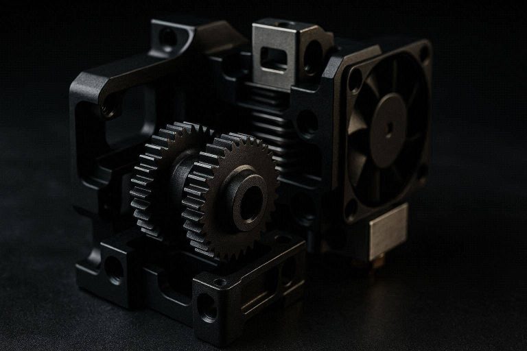
- Verify Mechanical Integrity: Ensure your dual-drive extruder gears are clean and free of caked plastic dust. Tighten your gantry belts and ensure your hotend cooling fan is operating at 100% efficiency.
Step 2: Generating the Volumetric Flow Ramp Test
Open OrcaSlicer and ensure your targeted printer profile and filament base profile are active.
- Navigate to the top menu bar and select Calibration > More > Max Volumetric Speed Test.
- A configuration dialog box will appear. For high-flow filaments, input a Start Volumetric Flow Rate of 5 mm^3/s and an End Volumetric Flow Rate of 40 mm^3/s. Set the Step increment to 0.5.
- Click OK. The slicer will automatically generate a specialized, hollow, elongated test tower featuring sweeping, continuous speed changes across its vertical axis.
- Slice the model. Change your preview color scheme selection from “Line Type” to Volumetric Flow Rate. You should see a flawless visual gradient transitioning from dark blue at the base (slow flow) to a bright red or orange at the top (extreme flow).
Step 3: Printing and Monitoring the Test Tower
Send the generated G-code to your machine. Sit next to the printer and observe the mechanical behavior during the run.
As the Z-axis rises, you will hear the pitch of your stepper motors change as the toolhead begins to travel faster on the straight perimeters. Listen closely to the direct-drive toolhead assembly.
Note the exact layer height if you begin to hear a rhythmic click… click… click sound. This noise is the extruder motor stalling or skipping micro-steps because it can no longer force the un-melted core of the filament into the nozzle barrel. Let the print continue until it either finishes or begins to structurally fail (gapping or tearing open).
Step 4: Forensic Analysis and Mathematical Calculation
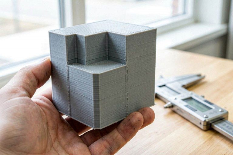
Once the print is complete, let the bed cool down completely before removing the model to prevent bending the thin-walled plastic structure. Hold the finished tower up to a bright, directional light source.
Look closely at the surface finish of the outer walls. High-flow polymers naturally exit the nozzle with a glossy, highly reflective finish when fully melted. As the volumetric flow rate begins to exceed the hotend’s thermal capacity, the plastic cools down. The surface finish will transition abruptly from highly glossy to a dull, rough, matte texture.
Further up the tower, you will see microscopic pits, followed by severe tearing and layer separation where the filament began to structurally fail.
- Take a high-precision digital caliper and measure the distance (in millimeters) from the absolute bottom of the tower up to the exact line where the glossy finish permanently turns matte, or where physical tearing begins. Let us assume this measured height is 42.5mm.
- Open the calibration documentation or use the explicit formula used by the slicer script to calculate your limit:
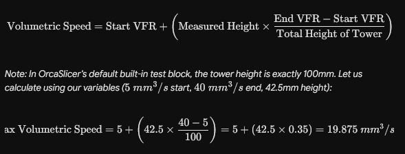
Your absolute, physical thermal failure threshold for this specific filament and hotend combination is 19.87 mm^3/s.
Step 5: Implementing the Safety Factor and Slicer Locking
Never input your absolute failure threshold directly into your production slicing engine. Operating at 100% of your hotend’s thermal capacity leaves zero margin for environmental real-world variables.
If the room temperature drops by 5°C, or if a specific section of your filament spool is slightly thicker (e.g., 1.78mm instead of 1.75mm), the nozzle back-pressure will immediately overwhelm the extruder, ruining your print.
Applying the 10% Safety Governor
Multiply your calculated maximum volumetric speed by a safety margin factor of 0.90:
19.87\text{ }mm^3/s \times 0.90 = 17.88\text{ }mm^3/s$$
Round this down to a clean 17.5 mm^3/s. This is your locked-in production ceiling.
Hardcoding the Ceiling
- Open your Filament Settings profile in OrcaSlicer or Bambu Studio.
- In the Basic Information tab, locate the input field titled Max volumetric speed.
- Erase the default preset number (which is often set conservatively to 12 or aggressively to 25) and enter your precisely calibrated 17.5.
- Save the profile under a distinct name, such as
Overture High-Flow PLA - Calibrated MVS.
Now, no matter how fast you set your linear print speeds in your global profile (even if you set your outer walls to 500 mm/s), the slicing engine will run an internal check against your volumetric limit. If a specific layer geometry threatens to exceed 17.5 $mm^3/s$, the slicer will autonomously throttle the linear speed downward, protecting the structural integrity of your part.
The Permanent Fix: High-Ticket Upgrades (Monetization Section)
Calibrating your software is an exceptional, zero-cost method to maximize your current hardware output. However, software tuning can only work within the strict physical boundaries of your factory machine. If your calibrated max volumetric speed settles at a disappointing 12 $mm^3/s$ or 15 $mm^3/s$, and you need to scale your output for high-volume commercial production, you must upgrade your hotend’s thermal melting architecture.
1. Upgrade to a Core Heating Technology (CHT) Nozzle
Standard nozzles feature a single, boring central cavity. When pushing high-flow filaments at high speeds, the core of the plastic remains insulated from the heated walls.
You must upgrade to an authentic Bondtech CHT Nozzle or a high-end aftermarket clone. CHT nozzles feature a patented internal copper splitter structure that physically divides the incoming 1.75mm filament into three separate micro-strands inside the melt zone. This exponentially increases the internal surface area contact by over 200%.
The plastic melts instantly and completely from the inside out. Installing an original CHT nozzle (available through industrial hardware networks via the MatterHackers or ShareASale affiliate portals) can instantly boost a stock hotend’s volumetric capacity from 15 $mm^3/s$ to over 28+ $mm^3/s$ without changing your stepper motors or heater cartridges.
2. High-Capacity Ceramic Zone Heaters
Most stock hotends utilize a traditional rectangular heater block clamped with a basic 40W cylindrical cartridge. This setup struggles to rapidly pump heat back into the block as mass volumes of cold filament continuously draw energy out of the system.
Upgrading your gantry to a 360-degree cylindrical Ceramic Ring Heater (60W or 80W) ensures absolute thermal responsiveness. Ceramic ring heaters wrap entirely around the melt zone barrel, transferring thermal energy uniformly into the polymer column. Sourcing these high-power hotend assemblies through trusted channels like PartnerStack or authorized Impact direct networks ensures your heater can maintain a rock-solid 220°C even under massive volumetric demands.
3. High-Torque Dual-Drive Extruder Upgrades
High-speed volumetric extrusion demands extreme force from your drive system to overcome the residual viscosity of the polymer. If your extruder relies on a single gear pushing plastic against a smooth roller, the filament will slip long before you hit your hotend’s true thermal ceiling.
Upgrading your toolhead to a CNC-machined, dual-drive geared extruder (such as the Bondtech LGX or an LDO Orbiter 2.0 system) provides dual-sided mechanical dominance over the filament. With a 3:1 or 5:1 gear reduction ratio, these lightweight premium extruders deliver incredible torque precision, allowing Klipper’s Pressure Advance commands to execute flawlessly without crushing or shaving your expensive high-flow polymers.
Preventative Maintenance Checklist for High-Flow Systems
To ensure your volumetric flow calibrations remain absolutely accurate and to prevent sudden extrusion drop-offs during long production runs, implement this strict preventative maintenance protocol:
- Blow Out Heatsink Fin Dust Weekly: Volumetric flow relies on a sharp thermal transition boundary. If your toolhead heatsink fan accumulates dust or lint, its cooling efficiency drops. Heat will creep upward, prematurely softening the filament core inside the cold zone and causing random under-extrusion jams that mimic an MVS failure. Clean the fins with compressed air every 50 print hours.
- Audit Thermistor Accuracy Monthly: Thermistors degrade over time due to constant high-temperature cycling. If your thermistor begins to report a temperature that is 10°C hotter than the actual nozzle core, your plastic will be under-melted, rendering your saved MVS value completely invalid. Run a PID autotune routine monthly to lock in electrical stabilization.
- Inspect Extruder Drive Teeth: High-flow filaments, especially matte and carbon-fiber filled variants, can leave microscopic bits of plastic shavings inside the teeth of your dual-drive gears. Over time, these shavings pack flat, reducing the gear’s ability to bite into the filament. Unload your filament and use a rigid brass wire brush to scrub the drive gear teeth clean.
- Perform a Regular Nylon Cold Pull: Pushing high-flow filaments to their absolute thermal boundaries can cause minor pools of stagnant polymer to bake and carbonize on the internal shoulders of the nozzle tip. This carbonized debris acts as a physical flow restrictor. Run a high-tension nylon cold pull every 150 hours of active print time to extract this internal debris and maintain flow purity.
By treating your 3D printer as a high-precision fluid dynamics system and executing systematic volumetric ramp testing, you eliminate speed guessing from your manufacturing workflow. Stop losing production hours to blind slicer adjustments, find your true physical limits, and start manufacturing with elite, industrial-grade accuracy.


2 Comments