7 Proven Fixes for PETG Over-Extrusion and Nozzle Scraping (Stop Failed Prints!)
There is no material in additive manufacturing as notoriously temperamental as PETG (Polyethylene Terephthalate Glycol). When printed correctly, it provides incredible structural integrity and heat resistance. However, if your settings are slightly off, PETG undergoes a thermodynamic transformation: it becomes a sticky, semi-molten goo that clings to your nozzle, accumulates in clumps, and eventually carves deep, scarred trenches into your model.
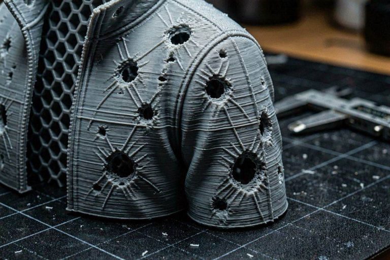
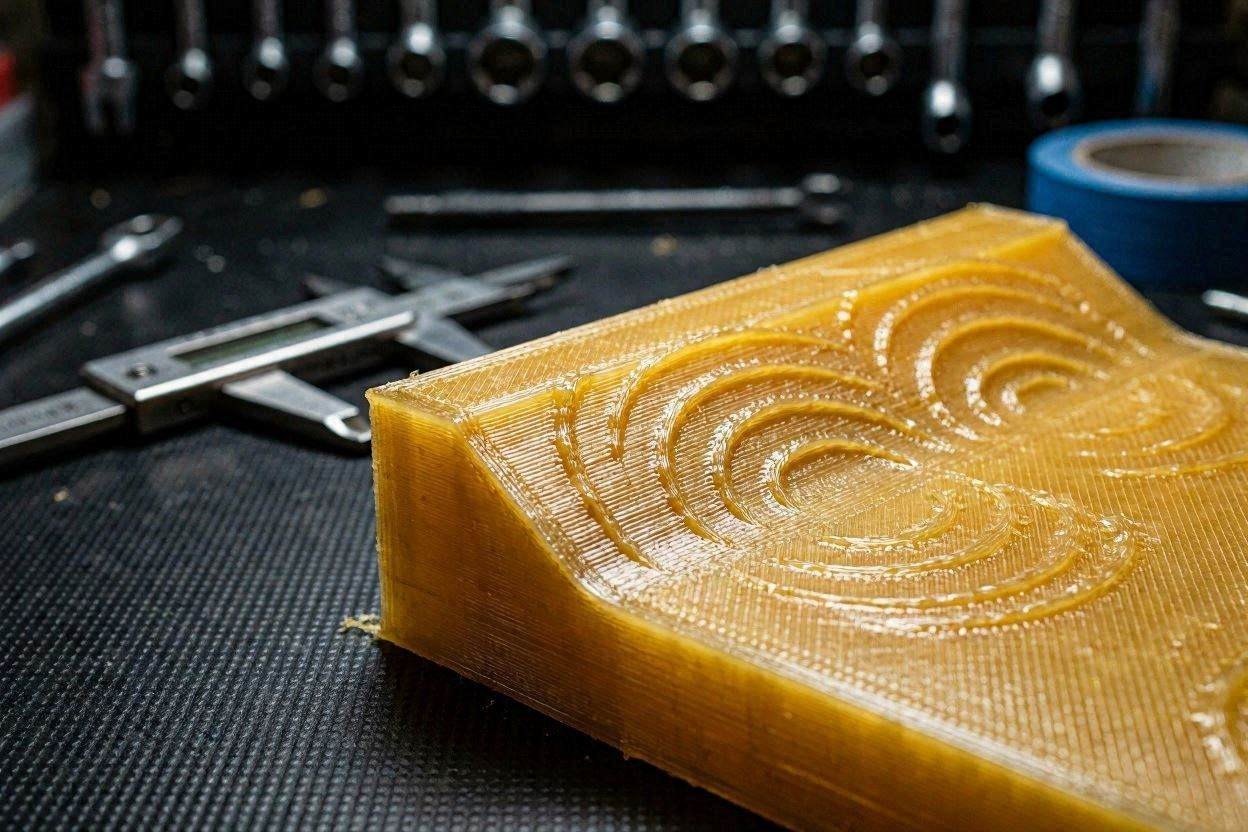
If you are currently watching your print head violently drag through a rough, pitted, and over-extruded top surface, you are experiencing the classic “Nozzle Scraping” artifact. This happens when the hotend extrudes just a fraction more plastic than the geometric path can accommodate. That excess material accumulates, cools slightly, and becomes a physical obstruction that the nozzle must plow through on every subsequent pass.
In this highly technical, comprehensive diagnostic manual, we will deconstruct the fluid dynamics of PETG extrusion. We will move beyond basic “lower the temperature” advice and explore the advanced kinematic workflows required to achieve industrial-grade PETG finishes. By the end of this guide, you will possess the exact engineering parameters required to permanently fix PETG over-extrusion and nozzle scraping.
The “Quick Answer” / Key Takeaways Box
- The Root Cause: Scraping is a feedback loop. Slight over-extrusion leads to material accumulation, which the nozzle then drags around, exacerbating the scarring on the next layer.
- The Temperature Factor: PETG is extremely sensitive to thermal dwell time. If you are printing at 250°C and dragging through the print, you are over-melting the polymer. Drop the temperature to 235°C to increase the plastic’s internal structural viscosity.
- Flow Multiplier: If your nozzle is scraping the top surface, your Flow Rate is likely 2–5% too high. Calibrate this using a single-wall hollow cube test.
- The Z-Offset Adjustment: If your print is otherwise perfect but the top shell is rough, your Z-offset is slightly too low, effectively “smushing” the plastic and reducing the available clearance for the toolhead.
- Volumetric Limits: High-speed printing requires a balance between speed and thermal recovery. If your volumetric flow exceeds the nozzle’s melt capacity, you will experience inconsistent, surging extrusion.
The Thermodynamics of PETG Scraping
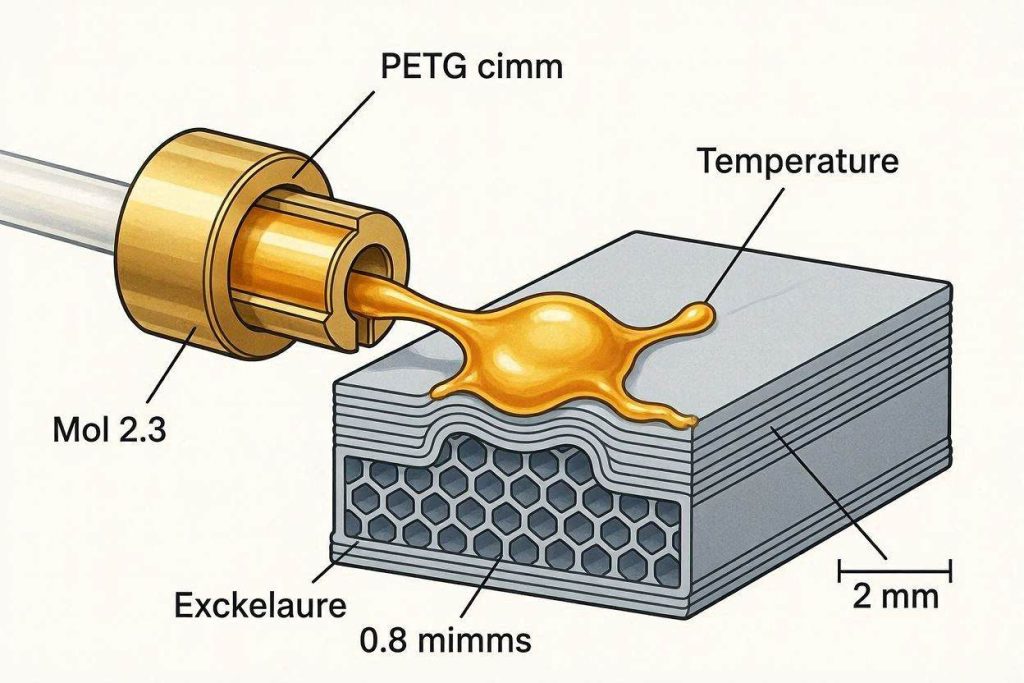
To successfully fix PETG over-extrusion and nozzle scraping, you must understand why PETG behaves differently than standard PLA. PLA freezes almost instantly upon leaving the nozzle. PETG, conversely, possesses a prolonged cooling curve. It remains in a “tacky” state for seconds after extrusion.
When you over-extrude PETG, that excess material does not just disappear. It stays sticky and accumulates on the nozzle tip. Once a small ball of PETG builds up on the nozzle, it acts like a soldering iron, physically melting and scarring the surrounding surface. As the toolhead continues to move, this clump grows, eventually scraping through the entire top layer of your print like a snowplow.
The artifact you see on your model is a physical history of this accumulation. To fix this, we must manipulate the extrusion pressure so that the nozzle remains clean and the material is deposited exactly within the intended geometric bounds.
Step 1: Precision Flow Rate Calibration
The most frequent culprit for surface scarring is an improperly calibrated Flow Multiplier (also known as the Extrusion Multiplier). Most slicer profiles use a default 1.00 (or 100%) flow rate. However, every spool of PETG has a unique density and chemical additives profile.
If you are over-extruding by even 3%, you are depositing 3% more plastic than the volume of the part requires. In a 10-layer print, that is 30% of a layer’s worth of excess plastic that has nowhere to go but up.
The Fix:
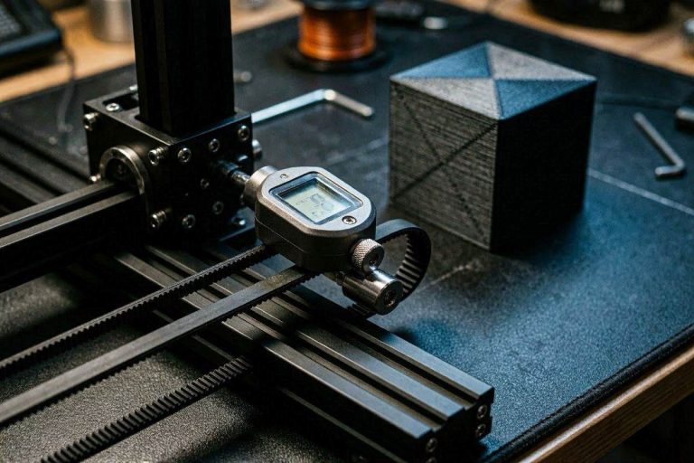
- Hollow Cube Test: Print a 20mm cube with 0% infill, 0 top layers, and exactly 2 walls (0.4mm nozzle).
- Calipers: Measure the thickness of the top edge. If you expect a 0.8mm wall (0.4mm x 2) but measure 0.84mm, your flow is high.
- Adjust: Apply the formula:
New Flow = (Expected Wall Thickness / Measured Wall Thickness) * Current Flow. - Reducing your flow to 0.98 or 0.97 (98% or 97%) is often the single most effective way to provide the nozzle with the clearance it needs to stop scraping.
Step 2: Thermal Management and Viscosity Control
You mentioned printing at 250°C. For many modern PETG formulations, 250°C is at the very upper threshold of stability. When you combine high temperatures with high-speed printing, you run the risk of over-melting the plastic to the point of structural collapse.
When PETG is printed at 250°C, it becomes significantly more “liquid” and runny. This promotes the exact oozing that creates the scraping clumps.
The Fix: Try lowering your print temperature to 235°C. By running cooler, the PETG maintains a higher structural viscosity (it is “thicker”). It will be less likely to ooze out of the nozzle during travel moves and less likely to accumulate as sticky clumps on the nozzle tip. Cooler PETG also cools and freezes faster, providing a firmer surface for the nozzle to glide over.
Step 3: Z-Offset and First Layer Precision
While scraping often occurs on the top layer, it is sometimes a symptom of a Z-offset that is slightly too low. If your nozzle is riding too close to the print, it is physically compressing the plastic into the surface, leaving absolutely no room for the next layer of material.
The toolhead effectively “crowds” the print. Every pass of the nozzle acts as a leveling tool, scraping through the plastic you just laid down because the nozzle tip has no air gap to pass over it.
The Fix: Increase your Z-offset by 0.02mm to 0.05mm. This microscopic change can be the difference between a toolhead that scrapes and a toolhead that glides. Use the Z-offset adjustment in your Bambu Lab or OrcaSlicer interface to “babystep” the print up just enough to create a clean, non-scarred extrusion path.
Step 4: Managing Infill and Top Layer Structure
If your outer walls are pitted, but your top surfaces are otherwise smooth, you may be experiencing “pillowing.” Pillowing occurs when your top layers are bridging across a sparse infill pattern (e.g., 10-15%).
As the molten PETG bridges the gaps, it sags significantly, creating a series of uneven hills. By the time the printer reaches the final top layer, these hills are physically higher than the intended Z-height, and the nozzle scrapes through them during its travel moves.
The Fix:
- Increase Infill Density: Bump your infill to 25–30% to provide a tighter supporting grid.
- Change Pattern: Use a structural infill pattern like Gyroid. Gyroid infill is non-overlapping, which prevents the “over-accumulation” of plastic at the infill/wall junction that often causes the scraping clumping to start.
Step 5: Pressure Advance (PA) Calibration
Pressure Advance (or Linear Advance) anticipates the pressure buildup inside your hotend and compensates for it by managing the extruder gear speed during cornering. If your PA value is incorrectly calibrated for PETG, the extruder will “surge” plastic at every single corner and at the end of every line.
If you don’t calibrate pressure advance for flexible filaments and PETG, you will always have these excess blobs of material at the start/stop points, which the nozzle will then drag across the rest of the print.
The Fix: Run an OrcaSlicer PA tower test. You are looking for the exact K-value where the corner remains sharp and square without exhibiting any bulging or rounding. A properly calibrated PA value will ensure that the flow stops the exact millisecond the motor reverses, keeping your nozzle tip clean and free of buildup.
[INTERNAL LINK: Placeholder for “How to Calibrate Pressure Advance for Flexible Filaments”]
Step 6: Avoiding Crossing Walls (Combing)
When the printer head travels across the top of your model, it often crosses over already-printed perimeters. If there is even a microscopic amount of over-extrusion, the nozzle tip will snag on the existing wall, creating a physical scar.
The Fix: In your slicer, enable Avoid Crossing Perimeters (often called Combing). This instructs the printer to route all travel moves exclusively over the infill areas or already-printed walls. By keeping the nozzle path away from the fresh, outer perimeters, you prevent the nozzle from physically “driving” through the walls of your print.
Step 7: The “Ironing” Feature
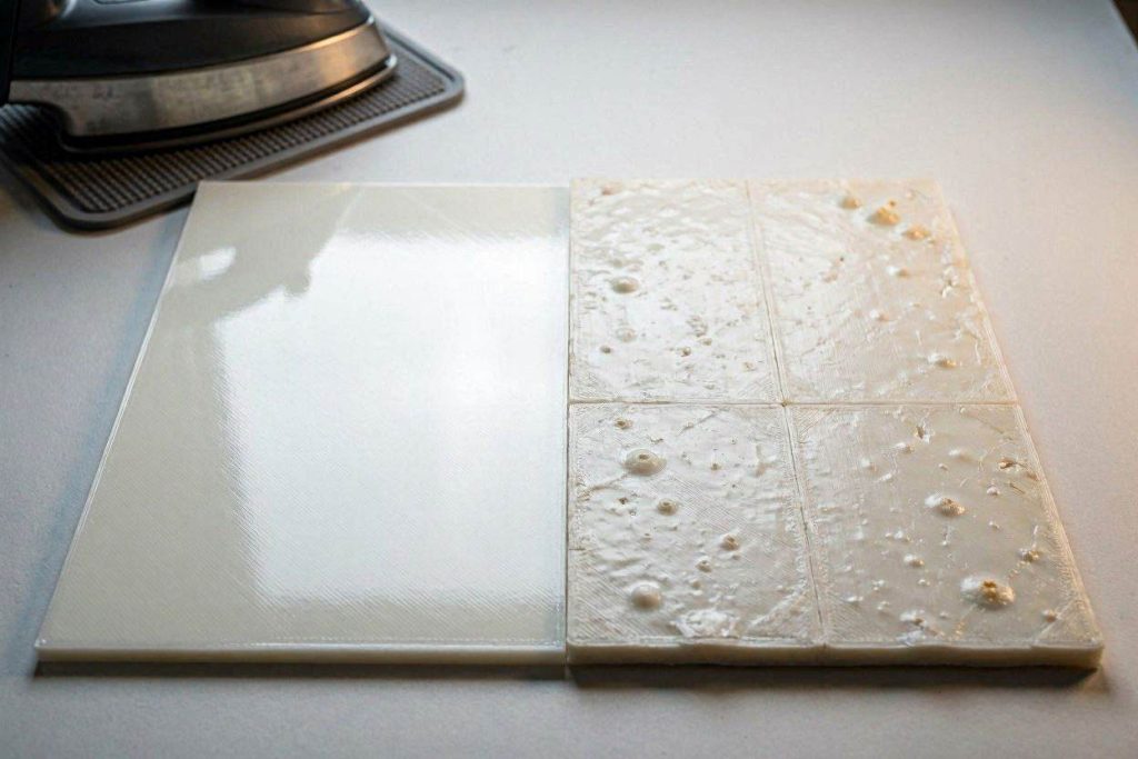
If you have tried everything and the top surface of your PETG print still appears slightly pitted or scarred, you can use the slicer’s Ironing feature.
Ironing is not another layer of plastic; it is a final, slow-speed pass where the nozzle remelts the very top surface of the print.
The Fix:
- Enable Ironing in your slicer.
- Set the Ironing Flow to 15-20%.
- Set the Ironing Speed to 20-30 mm/s.
- This pass will physically smooth out any micro-scratches or slight under-extrusion gaps left by the printing process, leaving a high-quality finish. Warning: Only enable ironing once you have fixed your over-extrusion, otherwise the nozzle will simply plow through the excess plastic.
Quick-Action Preventative Maintenance Checklist
To maintain your flawlessly smooth PETG prints and protect your hardware investments, implement this strict preventative maintenance protocol:
- Audit Your Filament Diameter: Inconsistent filament diameters cause localized over-extrusion. Measure your spool with digital calipers in 5 spots and input the average into your slicer profile.
- Clean the Nozzle Exterior: PETG is extremely sticky. Use a brass wire brush to scrub the nozzle exterior while heated before every single print. A dirty nozzle tip is the #1 cause of material accumulation and scraping.
- Verify Part Cooling: Ensure your part cooling fan is functional. If the fan is set to 0% for PETG, the plastic will remain gooey for too long, allowing the nozzle to drag and smear the surface. Increase fan speed to 20–40% for better layer definition.
- Purge the Melt Zone: Perform a nylon cold-pull every 100 hours of PETG printing to remove any carbonized material that could cause internal flow restrictions.
By treating your 3D printer as a high-precision fluid dynamics system and implementing these rigorous slicer calibrations, you will completely eradicate frustrating surface scarring. Stop accepting pitted prints, dial in your flow and temperature, and start manufacturing with elite, industrial-grade perfection.