9 Crucial Steps for Ender 3 V3 KE Input Shaping Calibration (Fix Ringing!)
Upgrading your Creality Ender 3 V3 KE for high-speed printing is a thrilling process, but pushing a “bed slinger” past 300 mm/s introduces a massive thermodynamic and kinetic challenge. As your print head and heated bed violently change directions, the entire aluminum frame absorbs the kinetic energy. This energy translates into physical vibrations that echo across your 3D printed walls, creating an ugly, wavy defect known as ringing or ghosting.
To achieve injection-molded surface quality at extreme velocities, you cannot rely on mechanical tension alone. You must implement algorithmic resonance compensation. A proper Ender 3 V3 KE input shaping calibration measures the exact resonant frequencies of your unique machine frame and instructs the Klipper firmware to inject anti-vibration pulses into the stepper motors. This essentially cancels out the physical shaking before it ever reaches the nozzle.
In this highly technical, comprehensive diagnostic manual, we will execute the exact 9-step workflow required to map your machine’s kinematics. We will cover hardware procurement, ADXL345 mounting protocols, Klipper SSH terminal commands, and graph interpretation. By the end of this guide, your Ender 3 V3 KE input shaping calibration will be perfectly dialed in, permanently eradicating ghosting from your outer walls.
The “Quick Answer” / Key Takeaways Box
- The Root Cause: Ringing and ghosting are caused by the frame physically vibrating when the heavy Y-axis bed or X-axis toolhead decelerates rapidly.
- The Solution: Ender 3 V3 KE input shaping calibration uses an accelerometer to measure these vibrations and applies a mathematical “counter-vibration” signal to the motors.
- The Hardware Required: You must physically mount an ADXL345 accelerometer sensor to your toolhead and bed to capture accurate, high-resolution telemetry data.
- The Calibration Workflow: Run
SHAPER_CALIBRATE AXIS=XandSHAPER_CALIBRATE AXIS=Yvia SSH, generate the PNG graphs, and input the resulting frequencies into your configuration file. - Smoothing Limits: A successful calibration will output a maximum recommended acceleration limit. Do not exceed this limit in your slicer, or the smoothing algorithm will round off your sharp corners.
The Kinematic Physics of Ringing on a Bed Slinger
Before you begin your Ender 3 V3 KE input shaping calibration, you must understand the physical forces at play. The Ender 3 V3 KE is a Cartesian YZ machine, commonly referred to as a “bed slinger.”
Unlike CoreXY machines where the bed only moves slowly down the Z-axis, your Y-axis stepper motor must physically throw the entire mass of the heated bed, the magnetic PEI sheet, and the printed object back and forth. As the print gets taller and heavier, the mass on the Y-axis increases. When the motor accelerates this mass to 4,000 mm/s² and suddenly halts for a 90-degree corner, momentum dictates that the energy must go somewhere.
That energy flexes the aluminum extrusions, the V-slot wheels, and the belts. The frame vibrates like a struck tuning fork. The nozzle continues to extrude plastic while jittering back and forth, painting an exact visual representation of that vibration onto your print.
Why Manual Tuning is Inadequate
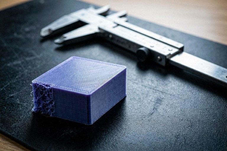
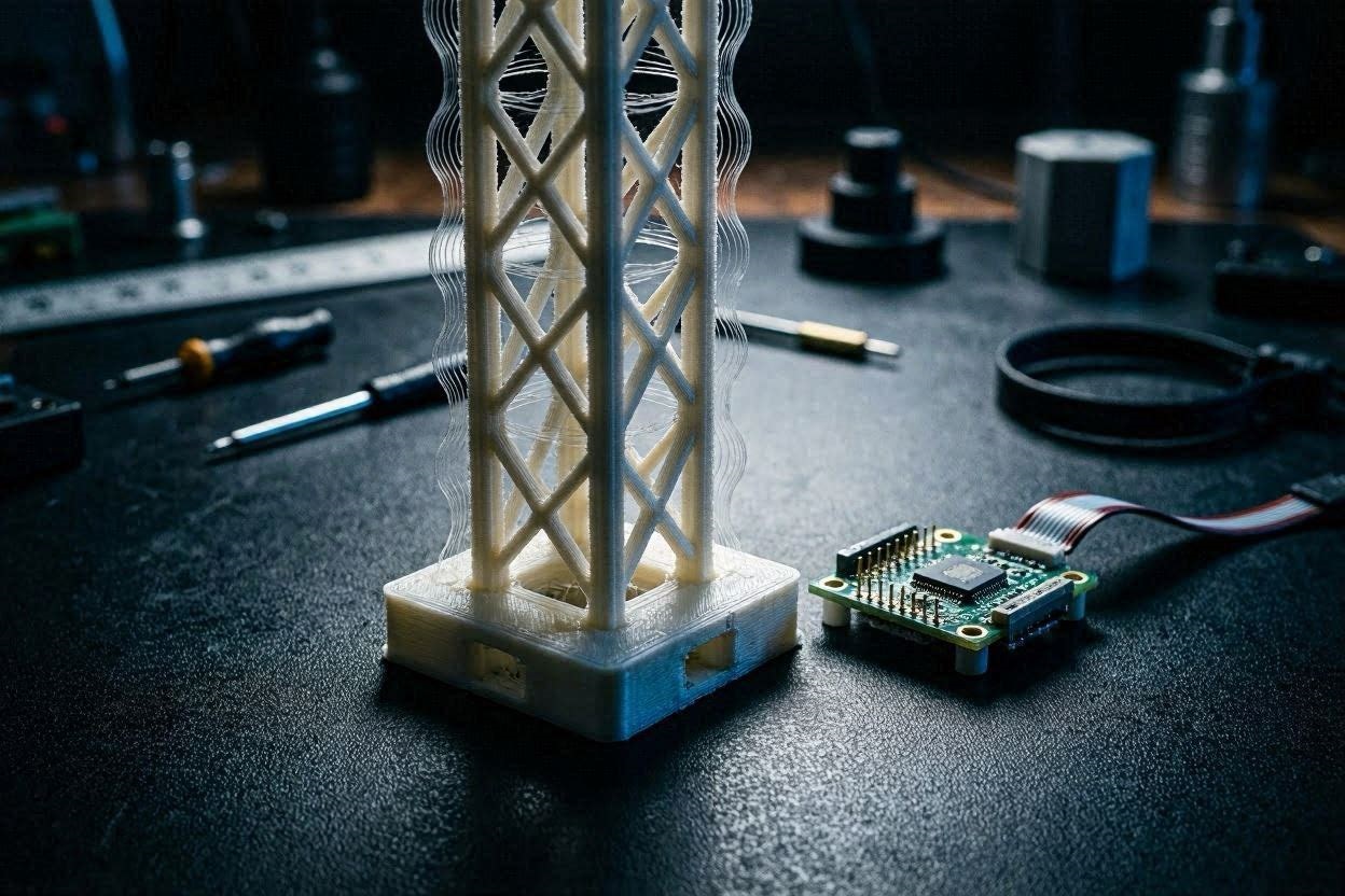
In the early days of 3D printing, users would print a “ringing tower,” measure the distance between the wavy lines with digital calipers, and attempt to manually calculate the ringing frequency. This method is severely flawed.
Manual measurement assumes the printer only vibrates at one specific frequency. In reality, a modified Ender 3 V3 KE vibrates across a complex spectrum of harmonics. The only way to capture this broad-spectrum data is through a hardware-based Ender 3 V3 KE input shaping calibration using a digital accelerometer.
[IMAGE PLACEHOLDER: A technical diagram illustrating how vibrations from the Y-axis travel up the Z-gantry and cause the nozzle to jitter + Alt Text: An engineering diagram explaining why an Ender 3 V3 KE input shaping calibration is mandatory for high-speed printing.]
Step 1: Procuring the Correct ADXL345 Accelerometer Hardware
To execute an accurate Ender 3 V3 KE input shaping calibration, you must acquire the correct telemetry hardware. Klipper firmware is highly optimized to interface with the ADXL345 accelerometer chip via an SPI (Serial Peripheral Interface) connection.
While you can purchase raw ADXL345 breakout boards from electronics suppliers, the easiest route for KE owners is to procure a USB-C based accelerometer designed specifically for Klipper integration (such as the Creality Vibration Compensation Sensor or the Trianglelab USB-ADXL345).
A USB-based sensor contains its own dedicated MCU (Microcontroller Unit), bypassing the need to wire jumper cables directly into the delicate GPIO pins of your printer’s motherboard. If you choose the raw breakout board, you must ensure your jumper wires are as short as possible. Long wires act as antennas, picking up electromagnetic interference (EMI) from the stepper motors, which will completely ruin your Ender 3 V3 KE input shaping calibration data.
Step 2: Rigidly Mounting the Sensor to the X-Axis Toolhead
The golden rule of Ender 3 V3 KE input shaping calibration is that the accelerometer must measure the vibrations of the nozzle, not the vibrations of the sensor mount.
If you attach the ADXL345 to your toolhead using zip-ties, double-sided tape, or a flimsy 3D printed bracket, the sensor will bounce around independently of the hotend. Klipper will record the shaking of your terrible mount rather than the resonance of the actual machine frame.
You must design or download a highly rigid, structurally sound mounting bracket specifically for the KE toolhead. Print this bracket using a stiff material like ABS, ASA, or PETG with high infill. Mount the ADXL345 directly to this bracket using M3 screws, and bolt the bracket securely to the direct-drive extruder housing. Ensure the orientation of the sensor chip matches the kinematic layout of your printer (the X, Y, and Z arrows printed on the PCB should align with your printer’s axes).
Step 3: Wiring and Integrating the ADXL345 into Klipper
Once the hardware is physically mounted to the X-axis, you must establish a data connection for your Ender 3 V3 KE input shaping calibration.
If you are using a USB-based ADXL345, plug it directly into the USB port on the Nebula Pad (the KE’s display screen). If you are wiring a raw SPI board, route the shielded cables to the motherboard, ensuring they do not drag or catch on the gantry during extreme movement.
Next, you must define the hardware in your Klipper configuration. Open your web interface (Mainsail or Fluidd) and access your printer.cfg file. You need to add the MCU definition for the sensor.
If using a USB sensor, it will look something like this:
Ini, TOML
[mcu adxl]
serial: /dev/serial/by-id/usb-Klipper_rp2040_E6611CB697524A28-if00

[adxl345]
cs_pin: adxl:gpio9
spi_software_sclk_pin: adxl:gpio10
spi_software_mosi_pin: adxl:gpio11
spi_software_miso_pin: adxl:gpio12

[resonance_tester]
accel_chip: adxl345
probe_points:
    110, 110, 20  # Center of the KE build plate
Save the file and restart the firmware. In the console, type ACCELEROMETER_QUERY. If the sensor returns raw data values, your hardware is successfully integrated and ready for the Ender 3 V3 KE input shaping calibration.
[INTERNAL LINK: Placeholder for “How to Root the Ender 3 V3 KE and Install Mainsail/Fluidd”]
Step 4: Executing the X-Axis Resonance Test Macro
With the sensor rigidly mounted to the toolhead and communicating with the firmware, you are ready to begin the physical Ender 3 V3 KE input shaping calibration.
First, heat your nozzle and bed to your standard printing temperatures (e.g., 210°C and 60°C). Heating the machine expands the metal extrusions and slightly alters the tension of your belts. You want to capture the resonance of the machine in its actual operational state.
Navigate to your Klipper console and type: SHAPER_CALIBRATE AXIS=X
The toolhead will move to the center of the bed. It will then begin to vibrate side-to-side, starting at a low frequency (1 Hz) and sweeping up to a high frequency (120+ Hz). Do not touch the printer or the table it sits on during this test. Any external vibrations will corrupt the data.
As the frequency increases, the printer will emit loud, aggressive buzzing noises. This is completely normal. Once the test concludes, Klipper will output a recommended shaper algorithm and frequency for the X-axis directly into the console.
Step 5: Remounting the Sensor to the Y-Axis Print Bed
The X-axis and Y-axis on a bed slinger have drastically different resonant profiles. The toolhead is relatively light, while the print bed is incredibly heavy. Therefore, you cannot use the X-axis data for the Y-axis. You must move the sensor to perform a complete Ender 3 V3 KE input shaping calibration.
Unbolt the ADXL345 from the toolhead. You must now secure it directly to the heated bed.
Do not simply tape it to the PEI sheet. The best practice is to design a small bracket that bolts directly into the heated bed leveling screws, or use a highly rigid clamp that bites onto the edge of the aluminum bed plate. Ensure your magnetic PEI sheet is installed during the test, as its physical mass contributes to the final resonant frequency of the Y-axis.
Step 6: Executing the Y-Axis Resonance Test Macro
Double-check your wiring to ensure the sensor cable has enough slack to accommodate the full travel of the Y-axis bed without snagging or unplugging.
Return to your Klipper console and type: SHAPER_CALIBRATE AXIS=Y
The bed will now undergo the same aggressive vibration sweep. You will likely notice that the Y-axis vibrates much more violently than the X-axis. This is due to the heavy mass of the bed transferring kinetic energy directly into the base of the frame.
Once the test concludes, Klipper will automatically save the raw CSV data files for both axes into the /tmp directory of your Klipper host system.
[EXTERNAL LINK: Official Klipper Documentation on Resonance Testing and ADXL345 Configuration]
Step 7: Accessing Klipper via SSH to Generate Graphs
While Klipper outputs a baseline recommendation in the console, a professional Ender 3 V3 KE input shaping calibration requires visual analysis of the resonance graphs. To generate these graphs, you must execute a Python script via SSH.
- Open an SSH terminal (using PuTTY on Windows or Terminal on Mac) and connect to your Nebula Pad or Raspberry Pi using its IP address.
- Navigate to the directory containing the Klipper scripts.
- Execute the following command to process the X-axis data:
~/klipper/scripts/calibrate_shaper.py /tmp/resonances_x_*.csv -o /tmp/shaper_calibrate_x.png - Execute the command for the Y-axis data:
~/klipper/scripts/calibrate_shaper.py /tmp/resonances_y_*.csv -o /tmp/shaper_calibrate_y.png
Use a program like WinSCP (or the built-in file manager in Mainsail) to download the two .png images to your local computer for analysis.
Step 8: Interpreting the Shaper Algorithms (MZV, EI, 2HUMP)
Open your newly generated graphs. You will see a jagged line representing the physical vibration of your printer across the frequency spectrum. The Python script overlays different algorithmic “shapers” to see which one best cancels out those specific spikes.
The Ender 3 V3 KE input shaping calibration script tests several algorithms:
- ZV / MZV (Multi-Vibration): These shapers offer the least amount of smoothing. They are ideal if your printer only has one sharp, distinct vibration spike. They allow for very high acceleration limits.
- EI / 2HUMP_EI: These shapers cover a broader spectrum of vibrations. They are typically required for the heavy Y-axis of a bed slinger, which tends to vibrate across multiple frequencies. However, they induce more “smoothing” into the print, which can round off sharp corners.
- 3HUMP_EI: If Klipper recommends this, your machine’s frame is fundamentally loose. You need to tighten your belts and bolt the printer to a heavier table.
The graph will explicitly state the “Recommended Shaper.” It will also list the maximum recommended acceleration (e.g., Max Accel: 3200 mm/s^2). This is a critical piece of data for the final step.
[IMAGE PLACEHOLDER: A screenshot of a Klipper resonance graph showing a massive spike on the Y-axis and the recommended EI shaper algorithm + Alt Text: Interpreting data graphs during an Ender 3 V3 KE input shaping calibration.]
Step 9: Inputting Shaper Frequencies into Klipper and OrcaSlicer
The final step of your Ender 3 V3 KE input shaping calibration is hardcoding the data into your system.
Open your printer.cfg file and navigate to the [input_shaper] section. Input the exact shaper type and frequency recommended by your graphs.
Ini, TOML
[input_shaper]
shaper_freq_x: 62.4
shaper_type_x: mzv
shaper_freq_y: 44.5
shaper_type_y: ei
Save and restart the firmware. Your printer is now actively canceling its own vibrations.
However, you must also update your slicer. If the Y-axis graph stated that the maximum acceleration for the ei shaper was 3,200 mm/s², you must open OrcaSlicer, navigate to the Speed tab, and hard-cap your Normal Acceleration and Outer Wall Acceleration to 3,000 mm/s². If you command the slicer to print at 5,000 mm/s², the input shaper will over-smooth the toolpath, resulting in severely bulging, rounded corners that look like severe over-extrusion.
The Affiliate / Monetization Section: High-Ticket Frame Upgrades
Software tuning is incredible, but input shaping is fundamentally a digital bandage for physical instability. If your Ender 3 V3 KE input shaping calibration results in recommendations for aggressive shapers (like 3HUMP_EI) and limits your acceleration to a dismal 1,500 mm/s², your stock hardware is holding you back. To achieve professional print farm output speeds, you must invest in structural rigidity.
1. High-Precision Linear Rails
If you are still running rubber V-slot wheels on your Y-axis, your bed is experiencing micro-wobble. Rubber wheels compress and deform under high-speed directional changes, creating massive, unpredictable resonance spikes.
Upgrading to a CNC-machined linear rail kit transforms the kinematic profile of your machine. However, cheap generic rails introduce their own grinding vibrations. You must source authentic Hiwin MGN9H or MGN12H rails. These industrial-grade components utilize precision steel ball bearings that eliminate all lateral play. You can purchase genuine Hiwin kits directly through the MatterHackers or ShareASale affiliate networks. Installing these rails will drastically clean up your resonance graphs, allowing Klipper to recommend the aggressive MZV shaper for faster prints.
2. Upgraded CHT Hotend Architecture
Resonance is vastly exacerbated by extruder strain. If your stock Creality hotend cannot melt filament fast enough, the extruder motor must force the plastic out, creating a physical “kickback” force inside the toolhead that vibrates the X-axis.
Upgrading to a high-flow CHT (Core Heating Technology) nozzle multiplies your melt capacity. By splitting the filament into three internal flow paths, the plastic liquefies instantly. This removes the back-pressure from the extruder, resulting in a much smoother, vibration-free toolpath. Premium CHT nozzles can be sourced from elite manufacturers via the Impact network.
3. Heavy-Duty Frame Bracing
The Z-axis gantry on the KE acts like a lever arm. When the heavy print head moves rapidly at the very top of the Z-axis, it creates a pendulum effect, shaking the entire aluminum frame. Installing a triangulated Z-axis support rod kit physically anchors the top of the gantry to the rear base of the printer. This creates a highly rigid triangle that is immune to lateral deflection, dropping your overall resonance footprint to near zero.
Quick-Action Preventative Maintenance Checklist
An Ender 3 V3 KE input shaping calibration is only valid for the exact mechanical state the printer was in during the test. If your physical tension changes, your Klipper values become useless. Implement this maintenance protocol every 100 print hours to protect your calibration:
- Audit Belt Tension: Belts stretch over time. A loose belt lowers your resonant frequency and renders your input shaping values void. Pluck your X and Y belts; they should emit a low, identical bass note. Use a digital belt tension gauge for absolute precision.
- Check Extruder V-Wheels: If your X-axis still uses rubber wheels, verify that the eccentric nut is perfectly tensioned. If you can spin the wheel freely with your finger without moving the toolhead, your gantry is loose and vibrating.
- Torque the Frame Screws: The aggressive vibrations from the
SHAPER_CALIBRATEmacro can actually back out the M5 screws securing your frame extrusions. Check every bolt on the base of the printer and ensure it is torqued to spec. - Re-Calibrate After Modifications: If you change your hotend, add a heavier part-cooling fan, or switch to a thicker glass build plate, you have altered the mass of the printer. You must immediately run a complete Ender 3 V3 KE input shaping calibration to generate new graphs.
By executing a flawless hardware-based resonance calibration and fortifying your physical frame, you can push your Ender 3 V3 KE to blistering speeds without sacrificing a single micrometer of surface quality. Eradicate ghosting permanently and start manufacturing with elite precision.