The Complete Guide to Upgrading Your 3D Printer Motherboard for Silent Stepping (2026 Walkthrough)
If your 3D printer sounds like a retro arcade machine screaming through a megaphone every time it prints a circle, you are experiencing the harsh reality of cheap, legacy stepper motor drivers. For years, manufacturers cut production costs by shipping stock machines with A4988 or generic A4982 stepper drivers. While reliable, these older components send blocky, aggressive electrical pulses to your motors, generating intense acoustic resonance that echoes through your entire workspace.
From an operational and environmental standpoint, the most impactful quality-of-life modification you can perform on a budget machine is executing a 3D printer motherboard upgrade specifically designed for silent stepping. By transitioning to modern Trinamic (TMC) stepper drivers, you physically alter the electrical waveform driving the motors, reducing the operational noise floor from a disruptive mechanical whine to a near-imperceptible whisper.
This comprehensive technical guide breaks down the exact acoustic mechanics of stepper motors, how to strategically select the right replacement mainboard to maximize your hardware ROI, and the precise structural workflow for a safe, successful installation.
Key Takeaways Box
- The Source of the Noise: Stock drivers use basic square-wave electrical pulses, causing the motor coils to snap violently. Silent drivers utilize advanced StealthChop technology to interpolate these pulses into smooth sine waves.
- Drop-In Replacements Lower Risk: Boards like the BigTreeTech SKR Mini E3 and Creality 4.2.7 are engineered to utilize the exact same mounting holes and connector layouts as stock Ender/CR-series boards, drastically lowering the technical barrier to entry.
- UART Communication unlocks Control: Upgrading to advanced drivers like the TMC2209 unlocks UART control, allowing you to adjust motor current (VREF) directly through your LCD screen or firmware interface instead of manually turning tiny potentiometers with a dangerous screwdriver.
- The Ferrule Safety Mandate: Never transfer factory-tinned power wires to a new motherboard. You must cut the tinned ends and crimp proper metal ferrules to prevent catastrophic thermal failure at the terminal block.
The Mechanics of Acoustic Resonance in 3D Printers
To understand why a motherboard swap completely transforms your manufacturing environment, you must first audit how stepper motors operate. A stepper motor does not spin freely like a standard DC motor. It contains internal electromagnets that are energized in a highly specific sequence to pull the central rotor in micro-movements, or “steps.”
When a legacy driver like an A4988 sends current to these electromagnets, it does so abruptly. This aggressive switching acts like a tiny hammer striking a bell thousands of times a second. The metal frame of your 3D printer then acts as an acoustic amplifier, broadcasting this resonance as a loud, musical whine.
[IMAGE PLACEHOLDER: A split graphic showing a jagged square electrical waveform representing legacy drivers next to a smooth, curved sine waveform representing modern TMC drivers + Alt Text: Visualizing the electrical waveform difference in a 3D printer motherboard upgrade for silent stepping.]
Modern drivers manufactured by Trinamic (such as the TMC2208, TMC2209, and TMC2226) utilize a proprietary technology called StealthChop. This algorithmic firmware smooths out the sharp electrical spikes, rounding the square waves into fluid voltage sine waves. The motor still hits its exact positional target, but the transition is so mathematically fluid that the acoustic vibration is almost completely eliminated. For a deep dive into the engineering behind these chips, consult the official documentation: [EXTERNAL LINK: Trinamic Stepper Motor Driver Architecture Specifications].
Selecting the Right Motherboard: Architecture and Ecosystems
When executing a 3D printer motherboard upgrade, you are faced with a strategic decision based on your long-term scaling goals: do you want a simple “drop-in” replacement, or a massive expansion board built for future custom kinematics?
1. The “Drop-In” Replacements (Maximum Efficiency)
If you own a high-volume consumer machine like a Creality Ender 3 or CR-10, several manufacturers have engineered boards with identical physical footprints to the stock mainboard. You do not need to print custom adapter brackets, and the wiring ports are located in the exact same positions.
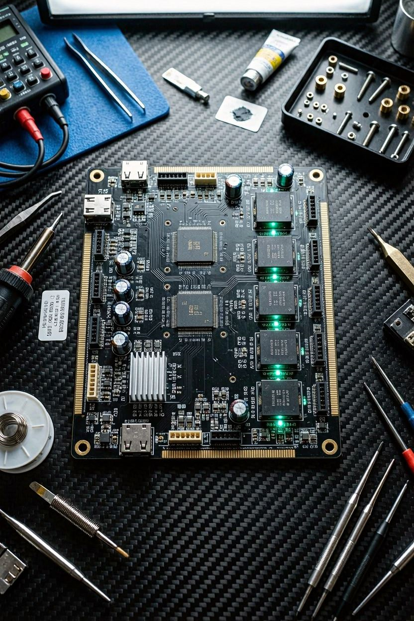
- BigTreeTech SKR Mini E3 (V2/V3): This is widely considered the gold standard for budget upgrades. It features integrated TMC2209 drivers running in UART mode, an upgraded 32-bit ARM Cortex processor, dedicated BLTouch/CR-Touch ports, and vastly improved thermal dissipation.
- Creality 4.2.7 “Silent” Board: The official upgrade path from Creality utilizes TMC2225 drivers. While highly reliable and incredibly easy to install (often shipping with pre-compiled firmware), it lacks the advanced UART current control and sensorless homing features of the SKR series.
2. The Expansion Boards (Built for Enterprise Scaling)
If you are planning to build a custom CoreXY machine (like a Voron), run dual extruders, or upgrade to high-voltage Klipper setups, you need a board with removable drivers and expansive I/O ports. Boards like the BigTreeTech Octopus or SKR V1.4 Turbo allow you to manually socket your own stepper drivers, support up to 8 independent motors, and offer multiple dedicated fan control circuits, making them the ultimate foundation for heavily modified production rigs.
Step-by-Step Motherboard Installation Workflow
Swapping a motherboard is essentially an exercise in extreme operational organization. If you hastily pull all the wires out at once, you will introduce massive failure points when initializing the new hardware.
Step 1: The Documentation Phase
Before unplugging a single wire, completely disconnect the machine from the wall power. Open the mainboard enclosure and take high-resolution, well-lit photographs of the existing wiring from multiple angles. Pay strict attention to the endstop cables (X, Y, Z limit switches) and the thermistor cables, as plugging these into the wrong ports on the new board can cause immediate firmware halts.
Pro Tip: Use small strips of masking tape and a fine-tip marker to label every single wire (e.g., “X-Motor”, “Hotend Fan”, “Bed Thermistor”) before removing them from the stock board.
+ Alt Text: ]
Step 2: The Ferrule Safety Mandate
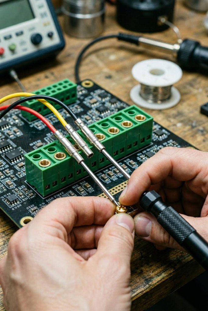
When you disconnect the thick red wires running from the power supply and the heated bed, look closely at the exposed metal ends. Budget manufacturers often coat these wire ends in solder (tinning) to keep them from fraying during factory assembly. This is a massive fire hazard. Solder “creeps” and deforms under the pressure of a screw terminal. Over time, the connection loosens, resistance spikes, and the terminal block physically melts.
Before inserting these high-current wires into your new motherboard, cut off the silver soldered tips, strip 5mm of fresh copper wire, and crimp on proper metal ferrules. This guarantees a solid, compression-proof mechanical connection that will never degrade.
Step 3: Physical Transfer and Seating
Remove the mounting screws holding the old board and carefully extract it. Seat your new motherboard into the enclosure. Reconnect the wires sequentially, cross-referencing your labeled tape and reference photographs. Ensure the polarity (positive/red and negative/black) is absolutely correct for the main power input and the part cooling fans. Reversing the main power polarity will instantly destroy the new board’s micro-controller.
Firmware Configuration: Waking Up the New System
A newly installed motherboard is essentially a blank slate. Unless you purchased a pre-flashed Creality 4.2.7 board for a specific Ender model, you will need to provide the board with its operating instructions.
The Marlin Compilation Approach
If you are sticking with standard Marlin firmware, you will need to compile a custom .bin file using Visual Studio Code and PlatformIO.
- Download the Marlin source code and the specific configuration files for your new motherboard architecture.
- In
Configuration.h, define your motherboard type explicitly (e.g.,#define MOTHERBOARD BOARD_BTT_SKR_MINI_E3_V3_0). - Define your new stepper drivers to activate the silent protocols. Change
#define X_DRIVER A4988to#define X_DRIVER TMC2209. - Compile the firmware, place the
.binfile on a blank MicroSD card, insert it into the powered-off printer, and turn it on. The screen will remain blank for roughly 15 seconds while the board flashes the new instruction set.
The Klipper Transition Workflow
Many operators use a 3D printer motherboard upgrade as the catalyst to transition away from Marlin entirely and adopt Klipper. Klipper offloads the heavy processing mathematics to a single-board computer (like a Raspberry Pi), using the new motherboard simply as a fast, localized I/O relay. To understand the full scope of transitioning operating systems, refer to our extended technical breakdown: [INTERNAL LINK: The Ultimate Guide to Migrating from Marlin to Klipper Firmware].
Post-Installation Calibration Audits
Once the printer powers on and navigates the LCD menu successfully, you must rigorously calibrate the new hardware before attempting a multi-hour production run.
- Motor Direction Check: Move each axis 10mm via the LCD screen. If an axis moves in the opposite direction it is supposed to, you must invert the motor direction in the firmware (or physically flip the cable connector 180 degrees, if your board allows).
- PID Autotune: Because you have connected the hotend and heated bed to brand new MOSFETs, the thermal algorithm will be slightly inaccurate. Run a standard PID Autotune (
M303 E0 S200 C8) to recalibrate the heating cycles. - VREF/Current Tuning: If you are using UART-enabled TMC2209s, navigate to the Advanced Configuration menu on your LCD and set your motor current (RMS). For standard NEMA 17 motors on an Ender 3, setting X, Y, and Z to 650mA and the Extruder to 800mA is a safe, cool-running baseline.
Strategic Critique: Stress-Testing the Concept
To ensure complete transparency in our technical advisory, we must subject this hardware modification workflow to a rigorous strategic evaluation.
What are the problems with this upgrade that we are not seeing?
The primary hidden consequence of upgrading to silent stepping is the unintended masking of mechanical failures. With loud, legacy A4988 drivers, the sheer volume of the motors often overshadows the sound of failing V-slot roller wheels, grinding linear bearings, or a nozzle scraping against the glass bed. Once the motors become dead silent, you will suddenly hear every single mechanical imperfection in your kinetic system. This often sends users down a frustrating, expensive rabbit hole of trying to silence the cooling fans and replace perfectly functional bearings, driving up the total cost of ownership significantly without actually improving print quality.
What assumptions are we making that might not be true?
We are moving forward under the assumption that the end-user possesses the fundamental electrical safety knowledge required to handle 24V direct current systems. Swapping a motherboard exposes the user to raw power supply rails. If an operator assumes that wire polarity does not matter, or ignores the absolute mandate to cut off tinned wires in favor of crimped ferrules, the resulting short circuit will not only destroy the newly purchased motherboard but could easily ignite the surrounding enclosure. We also assume the user is comfortable navigating complex firmware compilation environments like VS Code, which is a massive conceptual leap for an operator who has only ever used a basic slicing program.
If this exercise failed, what would be the most likely reason?
If a 3D printer motherboard upgrade fails catastrophically, it is almost exclusively due to rushed wiring transfers or poor documentation. Plugging a 24V endstop switch into a 5V thermistor port, or reversing the polarity on a high-draw cooling fan, will instantly fry the micro-controller unit (MCU) on the new board the moment the power supply switch is flipped. The second most common point of total failure is a corrupt firmware compilation—flashing a board with parameters meant for a distinctly different processor architecture will “brick” the board, requiring a highly complex bootloader recovery process using external programming hardware that most consumers do not own.