7 Powerful Steps to Fix an Extreme Sagging TPU Issue
If you are dealing with an extreme sagging TPU issue while attempting highly unconventional geometries, you are pushing your hardware to its absolute physical limits. Printing a cosplay head base using only 15% infill and zero outer perimeters with Sunlu 95A clear TPU is an incredibly ambitious mechanical challenge. When your friend succeeds with the exact same 3MF file but your printer fails, the problem lies deep within your specific hardware tolerances and local environmental variables.
Standard slicing profiles are designed around rigid polymers like PLA and PETG, which behave predictably under rapid cooling and high-speed toolhead movements. Thermoplastic Polyurethane (TPU), however, possesses unique viscoelastic properties that drastically alter how it bonds when suspended in mid-air. To resolve this failure, we must completely break down the thermal dynamics, Klipper kinematics, and hardware discrepancies affecting your machine.
This comprehensive diagnostic guide will walk you through the exact adjustments required to stabilize your flexible lattice structures. By implementing these 7 specific steps, you will permanently eliminate your extreme sagging TPU issue and achieve flawless, durable cosplay components.
The “Quick Answer” / Key Takeaways Box
- Step 1: Calibrate Actual Melt Zone Temperatures: Your 230°C might actually be 215°C due to factory thermistor variance. Run a custom temp tower to find your machine’s true ideal heat.
- Step 2: Optimize Minimum Layer Time: Without outer walls, the nozzle loops over small infill nodes too quickly. Increase your minimum layer time to at least 15 seconds.
- Step 3: Dial Back Aggressive Fan Profiles: Blaring your auxiliary fans at 100% is shock-cooling the TPU. This creates severe internal stress, dragging the structure down.
- Step 4: Transition to Continuous Infill: Switch from intersecting patterns like Grid to continuous paths like Gyroid to prevent the nozzle from plowing through soft plastic.
- Step 5: Tune Micro-Retraction and Combing: Turning retraction completely off causes oozing that pulls down layer lines. Enable a microscopic 0.4mm retraction with combing active.
- Step 6: Upgrade to a High-Flow Hotend: Stock brass nozzles create internal friction. Transition to a CHT nozzle to ensure uniform melting and prevent flow stuttering.
- Step 7: Implement Active Dehydration: Baking filament prior to printing is not enough. You must print directly from an active dryer to prevent ambient moisture absorption.
Understanding the Physics Behind an Extreme Sagging TPU Issue
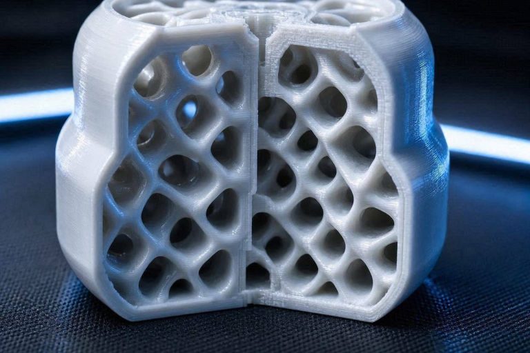
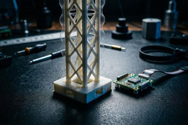
To successfully diagnose an extreme sagging TPU issue, we must examine the physical reality of what you are asking the 3D printer to achieve. By stripping away the outer walls (perimeters) of your model, you have removed the structural shell that normally contains and supports the internal infill. The printer is now effectively attempting to print a free-standing wireframe made of molten rubber.
When Sunlu 95A TPU exits the nozzle at 230°C, it is highly viscous and incredibly prone to stretching. Because there are no rigid walls to anchor the ends of the infill lines, the nozzle’s movement can easily drag the freshly laid, semi-molten plastic out of position. This dragging effect is the primary physical catalyst for sudden structural collapse.
Furthermore, TPU requires a delicate, perfectly metered balance of thermal energy to maintain its shape as it cools. If the ambient temperature around the toolhead fluctuates due to aggressive part cooling, the polymer chains will solidify at uneven rates. This uneven cooling creates localized shrinking, pulling the fragile infill lines downward and resulting in the severe drooping you are experiencing.
The 7-Step Resolution for Your Extreme Sagging TPU Issue
Resolving this specific extreme sagging TPU issue requires taking manual control away from the slicer’s default automatic profiles. While the Elegoo Neptune 4 Plus is a fantastic, high-speed Klipper machine, its default profiles are heavily optimized for rapid rigid polymer deposition. We must completely rewrite the thermal and speed variables for this unique geometry.
We will adjust the exact sequence of how the nozzle deposits the infill, how the fans interact with the polymer, and how the machine handles rapid travel moves. By optimizing these specific actions, you will stabilize the lattice structure and entirely eliminate the drooping artifacts.
Open your preferred slicer interface (such as OrcaSlicer or Elegoo Cura) and navigate to the advanced filament and cooling settings tabs. You must input these parameters manually to override the 3MF defaults your friend sent you.
Step 1: Calibrate Actual Melt Zone Temperatures
A common misconception in the 3D printing community is that sharing a 3MF file guarantees identical results across identical printer models. If your friend prints the file flawlessly, but you experience an extreme sagging TPU issue, the file itself is not the problem. The discrepancy is almost entirely based on hardware manufacturing tolerances.
No two thermistors or heater cartridges are identical out of the factory. Your friend’s printer might be reading 230°C while outputting a true 235°C, giving their TPU a slightly better, more fluid flow state. Your printer might be reading 230°C while only outputting 220°C, causing the TPU to drag and snag on the infill nodes because it is too cold.
To eliminate this variance, you must run a physical temperature tower test on your specific machine using the Sunlu 95A clear TPU. Download a specialized TPU temperature tower and slice it with your zero-wall, 15% infill parameters. Set the tower to range from 240°C down to 210°C in 5-degree increments.
Observe the tower carefully as it prints. You are looking for the exact temperature block where the infill lines remain taut and straight without stringing or sagging. Once you identify the perfect temperature for your specific Neptune 4 Plus, hardcode that exact value into your custom TPU filament profile.
Step 2: Optimize Minimum Layer Time for Wall-Less Infill
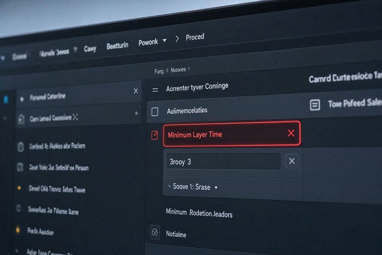
The absolute most critical software fix for an extreme sagging TPU issue on wall-less prints is adjusting the Minimum Layer Time setting. This parameter dictates the absolute fastest time the printer is allowed to complete a single layer. If the toolhead finishes the infill pattern in 3 seconds, the slicer will force it to slow down to meet the minimum threshold.
When printing a standard model, the toolhead spends considerable time tracing the outer walls, giving the internal infill plenty of time to cool. Because your cosplay head base utilizes zero walls, the toolhead is rapidly jumping from one infill node to the next. The plastic simply does not have the physical time required to harden before the nozzle returns to deposit the next layer.
This rapid deposition means you are essentially printing wet plastic on top of wet plastic. The structure quickly becomes a soft, heated mass that cannot support its own weight under gravity. Navigate to the “Cooling” tab in your slicer settings and locate the “Minimum layer time” parameter.
Set your Minimum Layer Time to a full 15 seconds. Ensure the “Minimum print speed” is lowered to around 10mm/s. This forces the extruder to move incredibly slowly on small cross-sections, giving the plastic ample time to freeze into place before the nozzle moves upward on the Z-axis.
Step 3: Dial Back Aggressive Part Cooling & Auxiliary Fans
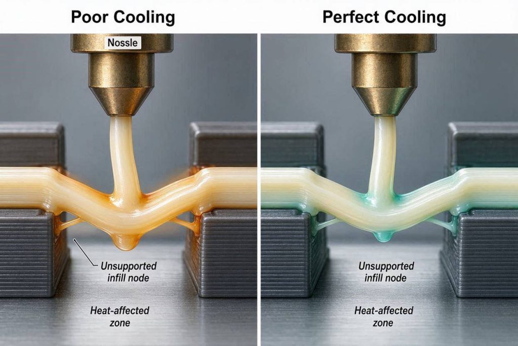
Your diagnostic notes indicate you are running the extruder fan at 80% and the massive auxiliary fan block at 100%. While TPU requires excellent cooling for long bridges, blasting a zero-wall infill structure with hurricane-force winds will actively cause an extreme sagging TPU issue. The sheer kinetic force of the air can push the flexible lines out of alignment.
Furthermore, shock-cooling Sunlu 95A causes severe internal warping stresses. When hot polyurethane is hit with 100% cooling air, the exterior skin shrinks rapidly while the core remains molten. This creates a thermal pulling effect that physically drags the delicate structure downward.
Drop your auxiliary fan completely to 0%; it is far too aggressive for delicate, slow TPU extrusion. Set your main extruder part-cooling fan to a maximum of 50%, and scale it down to 30% for standard infill moves. The goal is to gently solidify the polymer, not freeze it instantly while simultaneously blowing the fragile structure off its designated toolpath.
Step 4: Transition to a Continuous Infill Pattern
If your hardware is optimized and your temperatures are locked in, we must look at the specific infill geometry algorithms. Printing 15% infill without walls forces the slicer to make hundreds of tiny, rapid retractions and travel moves. You are currently running a conservative 5mm/s volumetric speed, which is generally very safe for TPU, but the pattern matters immensely.
If you are using a standard Grid or Cubic infill, the nozzle is forced to cross over its own previously laid lines on the exact same layer. When the nozzle hits an intersection, it physically plows through the semi-molten TPU. Without outer walls to hold the structure rigid, this plowing action will violently knock the infill out of alignment.
This continuous collision is a primary trigger for a severe extreme sagging TPU issue. Change your infill pattern to Gyroid or Honeycomb. Gyroid infill never crosses itself on the same layer; it prints in smooth, continuous, undulating curves that naturally dissipate structural stress.
This continuous flow completely prevents nozzle collisions. It dramatically increases the survival rate of unsupported flexible structures, allowing the TPU to stretch and bond naturally without being forcefully displaced.
Step 5: Tune Micro-Retraction and Avoid Crossing Perimeters
Your notes specify that you have retraction completely turned off. While turning off retraction absolutely prevents TPU from jamming in the extruder gears, it also means the nozzle oozes continuously during travel moves. This constant oozing drags hot plastic across the gaps, creating heavy stringing.
These thick strings physically connect independent pillars of your infill. As the strings cool and shrink, they act like tiny bungee cords, pulling down the structural lines and severely exacerbating the extreme sagging TPU issue. Instead of disabling retraction entirely, you must optimize it for flexible dynamics.
Re-enable retraction, but set the distance to a microscopic 0.4mm, and the speed to a very slow 15mm/s. This slight pressure relief prevents stringing without risking a gear jam inside the toolhead.
Additionally, enable the “Combing” or “Avoid crossing perimeters” setting in your slicer software. This forces the toolhead to travel entirely within the printed infill paths rather than moving across the empty open spaces. By keeping the travel moves over already printed plastic, any residual oozing simply blends into the structure rather than creating destructive horizontal strings.
Step 6: The Permanent Fix (Premium Hotend Upgrades)
Sometimes, software tweaks are simply not enough to overcome the physical hardware limitations of consumer-grade components. If you have optimized your layer times and cooling, but the extreme sagging TPU issue persists, you must look at your core extrusion ecosystem. Standard brass nozzles create significant internal friction that hinders the smooth flow of viscoelastic materials.
When printing fast or with thick layer heights, the internal friction inside a cheap nozzle causes the flow rate to stutter microscopically. This stuttering leads to under-extruded infill lines that immediately break and droop. The permanent fix is transitioning to a premium, high-flow hotend ecosystem to guarantee unyielding reliability.
Upgrade to a precision-machined bi-metallic heatbreak and a specialized CHT (Core Heating Technology) nozzle via reputable enthusiast affiliate networks like ShareASale or directly through MatterHackers. These premium components feature highly polished internal pathways that drastically reduce friction against the soft TPU filament.
A CHT nozzle mechanically splits the filament into three separate melt zones, ensuring the TPU is heated uniformly directly to the core. This uniform heating guarantees a mathematically perfect extrusion bead that bonds instantly to the layer below it. Upgrading your hotend ecosystem will completely eliminate the flow-stuttering artifacts that cause structural collapse.
Step 7: Implement Active Professional Filament Dehydration
You mentioned drying the Sunlu 95A at 55°C for 12 hours, which is an excellent baseline practice. However, TPU is aggressively hygroscopic, meaning it acts like a sponge for water vapor. The exact moment you remove it from the dryer and mount it to the printer spool holder, it begins absorbing ambient room humidity.
Depending on your local climate, within two hours the outer layers of the spool will be wet enough to cause popping. When this moisture turns to steam inside the 230°C melt zone, it explodes out of the nozzle orifice. These microscopic explosions sever the delicate infill lines you are relying on for your cosplay head base, immediately causing an extreme sagging TPU issue.
To ensure moisture never ruins your long prints, you need a dedicated, active heated filament management system. You must print with the spool residing entirely inside the dryer.
Solutions like the Sunlu S4 or premium active dryers available through Impact or MatterHackers allow you to bake the moisture out while actively feeding it into the printer. Running your TPU directly out of a heated chamber ensures the polymer enters the extruder gear assembly in a perfectly pristine, predictable state for the entire 12-hour print duration.
[INTERNAL LINK: Placeholder for related article titled “First Layer Not Sticking? How to Fix 3D Print Warping & Spaghetti”]
Preventative Maintenance Checklist for Flexible Polymers
To ensure your Klipper ecosystem remains highly stable and you never experience a catastrophic extreme sagging TPU issue again, integrate these critical checks into your regular machine maintenance workflow:
- Scrub the Drive Gears: Disassemble your toolhead cover and use a stiff nylon brush to clean the teeth of your dual-drive gears. TPU frequently leaves microscopic rubber dust packed into the gear teeth, severely limiting their grip for future complex prints.
- Verify Firmware Offsets: Check your Klipper configuration file and ensure your Pressure Advance is tuned specifically for this spool of Sunlu 95A. Incorrect pressure values will violently under-extrude your delicate infill intersections.
- Perform a High-Temp Cold Pull: The low-speed printing required for TPU often allows degraded plastic to carbonize on the inner walls of the nozzle. Perform a high-temperature nylon cleaning pull to extract this debris and restore your nozzle’s perfect internal flow geometry.
- Check V-Roller Tension: If the rubber V-wheels on your X and Y axes are slightly loose, the rapid back-and-forth infill movements will cause the toolhead to shudder. Tighten the eccentric nuts until the carriage is perfectly firm to protect the dimensional accuracy of your lattice.