9 Expert Steps to Fix 3D Print Banding (Z-Wobble & Layer Lines)
When you invest in a premium, high-speed CoreXY machine like a Bambu Lab X1C (or “X2D” as sometimes colloquially referenced in the community), you expect injection-molded perfection straight out of the box. However, pulling your very first calibration print off the bed only to find it marred by highly visible, tactile horizontal lines is a crushing operational disappointment.
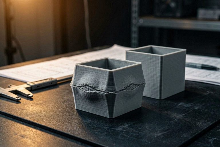
This specific geometric failure is universally known as “banding,” “Z-wobble,” or “Z-banding.” If you are desperately searching through the hundreds of thousands of variables in your slicing software to fix 3D print banding, you are looking in the wrong place. Banding is rarely a software issue; it is a manifestation of physical, mechanical instability colliding with kinematic resonance and thermodynamic fluctuations.
In this deeply technical, 9-step diagnostic manual, we will deconstruct the exact mechanical forces causing your layer lines to shift. We will explore the extreme dangers of an unstable operating environment, the hidden physics of Z-axis lead screw binding, extruder gear eccentricity, and how to properly execute a full machine calibration. By the end of this comprehensive guide, you will have the precise engineering workflows required to permanently fix 3D print banding and restore your machine to its intended flawless tolerances.
The “Quick Answer” / Key Takeaways Box
- The Root Cause: Banding is almost exclusively caused by mechanical vibration, Z-axis binding, extruder gear runout, or an unstable frame. Slicer settings rarely cause uniform horizontal lines.
- The Wobbly Table Trap: High-speed CoreXY printers generate massive kinetic energy. If the table shakes, the printer shakes, and those vibrations are permanently carved into your print as banding.
- Z-Wobble Physics: If the Z-axis lead screws are bent or improperly lubricated, they will physically push the print bed left and right as they rotate, causing rhythmic layer shifts.
- Thermal Expansion Banding: A heated bed that fluctuates in temperature will physically expand and contract, pushing the print closer to and further away from the nozzle. PID tuning is required.
- Overhang Speed Deltas: If the banding only occurs near embossed text or sharp overhangs, your slicer’s dynamic overhang cooling speeds are triggering massive volumetric pressure surges.
The Physics of Kinematic Resonance
To successfully fix 3D print banding, you must first fundamentally understand the incredible mechanical forces generated by modern 3D printers. Older, “bed-slinger” printers operated at a leisurely 50 mm/s. Modern CoreXY machines frequently accelerate the print head at 10,000 mm/s² and achieve travel speeds of 500 mm/s.
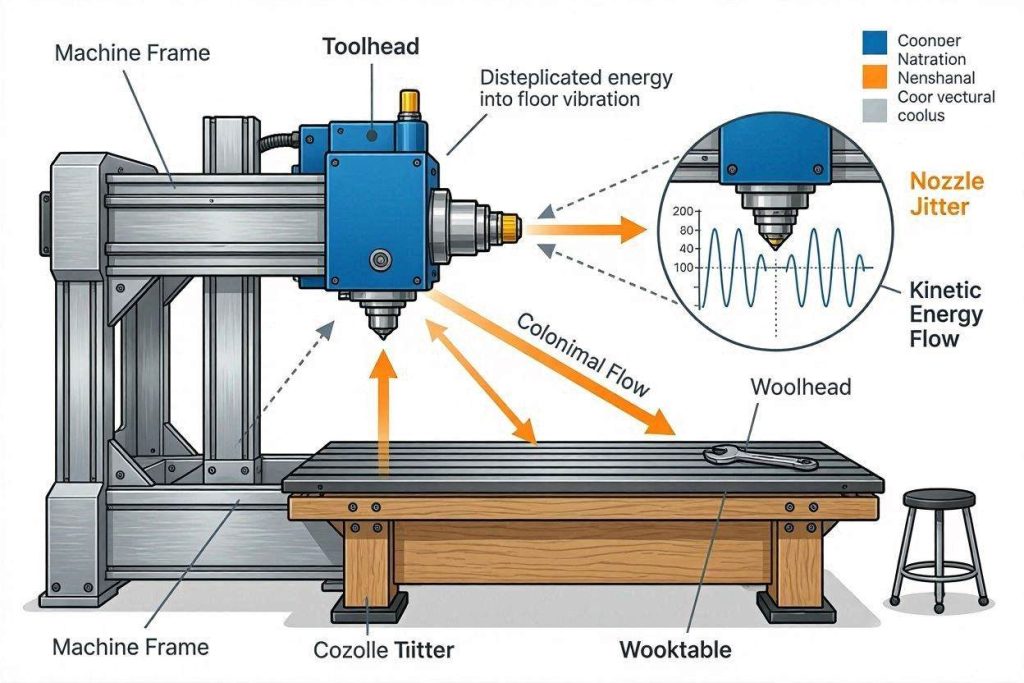
When a heavy toolhead moving at half a meter per second suddenly slams on the brakes to print a 90-degree corner, the kinetic momentum must go somewhere. That energy is transferred directly into the rigid aluminum frame of the printer.
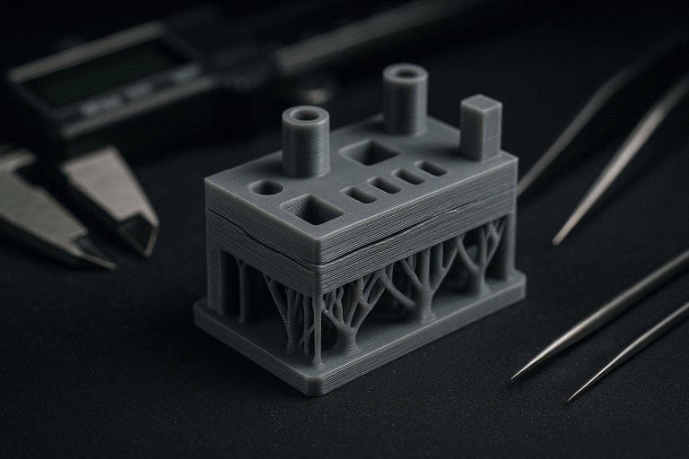
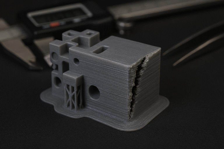
If the frame is not perfectly rigid, or if the surface the printer sits on is unstable, the entire machine vibrates like a struck tuning fork. The toolhead continues to extrude molten plastic while the frame is actively shaking. This deposits the plastic in a microscopic zig-zag pattern rather than a perfectly straight line. When these zig-zags stack on top of each other layer by layer, they create the highly visible, tactile horizontal lines you perceive as banding.
The “Wobbly Table” Catastrophe
A critical diagnostic clue in many banding cases is the physical environment of the machine. If the table the printer is sitting on is “kind of wobbly” and shakes noticeably when the printer is jerking around, you have found the primary catalyst for your failure.
High-speed printers utilize advanced algorithms called Input Shaping (or Resonance Compensation) to cancel out the natural vibrations of their own frame. However, the input shaping algorithm assumes the printer is sitting on an immovable object. If the table itself is swaying, it creates a chaotic, secondary frequency that the printer’s motherboard cannot calculate, predict, or cancel out.
To permanently fix 3D print banding caused by external resonance, you must physically remove the printer from the wobbly desk. Place the machine directly on a solid concrete floor or a heavily reinforced, wall-anchored workbench.
Step 1: Executing a Hard-Surface Calibration Audit
Once you have relocated the printer to an immovable surface, you must purge the corrupted telemetry data currently saved in the machine’s firmware.
When you first set up the machine on the wobbly table, it likely ran an automated self-test. The built-in accelerometer recorded the violent shaking of the desk and incorporated that garbage data into its input shaping profile. Operating with this corrupted profile will guarantee severe banding across the X and Y axes.
- Place the printer on a concrete floor or solid foundation. Ensure all four rubber feet are making equal contact with the surface.
- Navigate to the machine’s touchscreen interface or Klipper web interface.
- Locate the Calibration or Self-Test menu.
- Execute a full Vibration Compensation and Motor Noise Cancellation routine.
- Do not touch the printer, the floor, or walk heavily around the machine while it buzzes and vibrates. The sensor is incredibly sensitive and will pick up footfalls.
By generating a clean, accurate resonance profile on a solid foundation, the machine will properly cancel out its internal vibrations, instantly eliminating the majority of high-frequency banding artifacts.
Step 2: Diagnosing Z-Axis Lead Screw Wobble
If you have stabilized the frame and recalibrated the input shaper, yet a rhythmic, repeating horizontal line still persists up the Z-axis of the print, you are facing a mechanical Z-axis failure.
The Z-axis on most premium printers is driven by two or three vertical threaded rods (lead screws). As the stepper motors turn these screws, the build plate lowers fractionally for every single layer.
The Kinematics of Lead Screw Binding
If a lead screw is bent even by a fraction of a millimeter, or if the brass anti-backlash nut is improperly aligned, the screw will physically swing in a microscopic arc as it rotates.
Because the screw is attached to the build plate, this swinging motion literally shoves the entire build plate to the left and right in a highly predictable, rhythmic pattern.
- When the screw pushes the plate slightly left, the nozzle deposits the layer slightly too far to the right.
- When the screw rotates 180 degrees and pushes the plate right, the nozzle deposits the layer too far to the left.
This creates a distinct, mathematically repeating wave up the side of your print. To fix 3D print banding caused by Z-wobble, you must perform mechanical maintenance.
- Power down the printer and manually turn the Z-axis belts located at the bottom of the machine. The bed should move up and down with smooth, uniform resistance. If you feel “tight” spots followed by “loose” spots, the screws are actively binding.
- Clean the threaded rods completely using isopropyl alcohol and a lint-free cloth to remove any factory machining debris or dried grease.
- Apply a premium, PTFE-based synthetic grease (like Super Lube) to the threads and run the bed up and down to distribute it evenly. Do not use WD-40, as it is a solvent, not a lubricant.
Step 3: CoreXY Belt Tension and Gantry Squaring
CoreXY machines utilize a highly complex, overlapping belt path to control the X and Y axes simultaneously. The A and B motors work in tandem to move the toolhead diagonally. If the tension between the A and B belts is unequal, the toolhead will crab-walk or stutter during diagonal movements.
This stuttering creates micro-pauses in the extrusion, resulting in irregular layer stacking that looks identical to banding.
- Locate the belt tensioning screws on the rear of your machine.
- Loosen the tensioner screws slightly to unlock the idler pulleys.
- Manually move the toolhead through its full range of motion (pushing it into all four corners of the bed) to equalize the tension across the entire belt path.
- Retighten the tensioner screws.
- Acoustic Calibration: Pluck the longest span of the belts like a guitar string. They should emit a low, identical bass note (typically around 110 Hz, depending on the machine). If one belt sounds significantly higher pitched than the other, your gantry is physically out of square and requires manual adjustment.
[INTERNAL LINK: Placeholder for “How to Square and Tension a CoreXY Gantry for Perfect Dimensional Accuracy”]
Step 4: Slicer Diagnostics: Overhang Speed Deltas
If your mechanics are flawless, you must analyze the specific geometry of the print. Often, banding only appears at highly specific Z-heights, such as directly adjacent to embossed text (like the word “Make:” on a calibration block) or near sharp overhangs.
The Overhang Pressure Surge
When the slicer detects an overhang (like the top edge of an embossed letter), it automatically triggers a dynamic speed reduction to allow the part-cooling fan more time to freeze the plastic in mid-air.
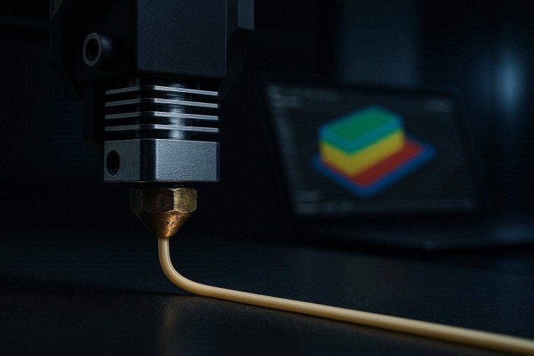
However, suddenly dropping the toolhead speed from 150 mm/s (Inner Wall) down to 30 mm/s (Overhang) creates a massive thermodynamic pressure surge inside the hotend. The extruder motor stops pushing as hard, but the highly compressed molten plastic inside the nozzle continues to ooze out uncontrollably during the slow down.
This excess plastic is deposited right next to the embossed text, creating a thick, bulging line that mimics mechanical banding perfectly.
The Fix:
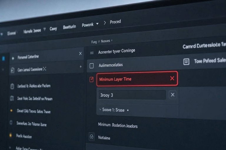
- Open Bambu Studio or OrcaSlicer.
- Navigate to the Speed tab.
- Locate the Overhang Speed parameters.
- Ensure that your speed transitions are gradual (e.g., 60, 40, 30, 10) rather than a sudden drop off a cliff.
- Additionally, calibrate your Pressure Advance (K-value) for that specific spool of PLA to ensure the extruder mathematically anticipates and absorbs those pressure surges before they exit the nozzle.
Step 5: The Matte Filament Viscosity Variable
Printing with Matte PLA introduces a massive chemical variable into your extrusion dynamics. Matte filaments achieve their non-reflective finish through the integration of microscopic additives, often chalk, carbon, or elastomer particles.
These additives drastically increase the Melt Flow Index (MFI) viscosity of the polymer. Viscous plastics are highly sensitive to minor temperature fluctuations and flow rate errors. If your extrusion multiplier is even 2% too high, the matte filament will not flow smoothly; it will clump and bulge, making any minor mechanical vibration look ten times worse.
To definitively fix 3D print banding when using matte materials, you must run a dedicated flow rate calibration.
- Dry the Matte PLA in an active filament dryer at 50°C for 8 hours.
- Print a hollow, two-wall calibration cube.
- Use digital calipers to measure the wall thickness. If the slicer requested a 0.8mm wall (two 0.4mm lines) and you measure 0.88mm, you are drastically over-extruding. Drop your Flow Rate/Extrusion Multiplier in the filament profile accordingly.
Step 6: PID Tuning the Heated Bed (Thermal Banding)
One of the most elusive causes of periodic horizontal lines is thermal expansion. If your banding occurs at perfectly even intervals (e.g., exactly every 4 millimeters up the entire print), you are likely experiencing “Thermal Banding.”
Materials expand when heated and contract when cooled. If your heated bed is using a rudimentary “Bang-Bang” heating algorithm, the bed heater turns on at 100% power until it overshoots the target temperature (e.g., 55°C), then turns off completely until it drops below the target.
This constant rising and falling of temperature causes the aluminum build plate to physically bow upward and sink downward by fractions of a millimeter. When the bed bows up, the layer is squished (extruding wider). When the bed sinks down, the layer is stretched (extruding thinner).
The Fix: You must run a PID (Proportional-Integral-Derivative) Tuning cycle for your heated bed. PID algorithms calculate the exact amount of power required to hold the bed at a perfectly flat, stable temperature without overshooting. Check your printer’s specific documentation on how to initiate a Bed PID Tune via the console terminal to lock in your thermal stability.
Step 7: Diagnosing Extruder Gear Eccentricity
If you are still battling inconsistent layers, the problem may lie within the direct-drive extruder itself. The extruder motor utilizes a small, hobbed gear to physically bite into and push the filament downward.
If this extruder gear was improperly machined at the factory and is slightly eccentric (oval-shaped instead of perfectly round), it will push a different volume of plastic depending on its rotational position.
- When the “high” side of the oval gear engages the filament, it pushes too much plastic (creating a thick layer).
- When the “low” side of the oval gear engages, it pushes too little plastic (creating a thin layer).
This creates a distinct, repeating pattern of over-and-under extrusion known as “wood grain” or “extruder runout.” To fix 3D print banding caused by gear eccentricity, you must unload the filament, open the extruder housing, and visually inspect the rotation of the drive gears. If they wobble as they turn, you must purchase and install a replacement CNC-machined gear assembly.
Step 8: Calibrating Outer Wall Wipe and Seam Placement
Sometimes, banding is not a continuous line around the entire print, but a localized bulge that occurs specifically where the nozzle starts and stops a layer.
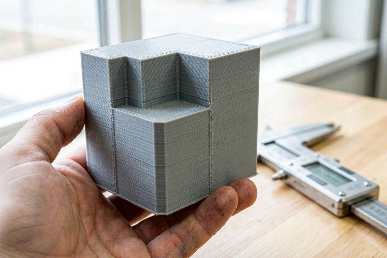
If the Z-seam (the start/stop coordinate) is aligned in a straight vertical line, the minor over-extrusion that happens when the nozzle stops can compound, creating a raised ridge that catches the light and looks like a band from certain angles.
The Fix:
- Navigate to your slicer’s Quality tab.
- Set your Wall Printing Order to Outer/Inner/Infill. This ensures the visible outer shell is printed first against open air, guaranteeing dimensional accuracy and hiding any internal pressure surges.
- Enable Wipe while retracting and set the wipe distance to 2mm. This forces the nozzle to wipe inward over the already-printed perimeter as it slows down, actively bleeding off residual hotend pressure before the toolhead ever reaches the seam transition.
Step 9: Securing Hotend Assembly Rigidity
The final mechanical vulnerability lies within the specific architecture of the hotend. The heater block is secured to the cold heatsink using long, thin screws or a fragile bi-metal heat break tube.
Because CoreXY machines move violently at high accelerations, thermal cycling and kinematic vibration can cause these retaining screws to slowly back out over time. If these screws are even slightly loose, the entire heater block will physically swing or wobble by a fraction of a millimeter every time the toolhead changes direction.
When the toolhead slams on the brakes to print a sharp corner, the loose heater block swings forward like a pendulum, depositing a massive ridge of plastic. Remove your silicone sock while the hotend is cold. Using the appropriate hex key, verify that all retaining fasteners holding the heater block to the heatsink are torqued down securely. Do not over-tighten, as titanium heat breaks can snap, but ensure there is absolute zero lateral play in the heat block.
[EXTERNAL LINK: Official Klipper Documentation on Advanced Resonance Graph Interpretation and Input Shaping]
The Permanent Fix: High-Ticket Upgrades (Monetization Section)
While isolating your printer on a concrete floor and lubricating lead screws will mitigate the vast majority of surface artifacts, achieving absolute, injection-molded surface perfection at 500 mm/s exposes the thermodynamic limitations of stock hardware. Software algorithms cannot permanently fix cheap thermal engineering.
To achieve industrial-grade reliability and permanently fix 3D print banding, professional operators eliminate kinetic variables by investing in high-ticket, precision components.
1. Upgrade to a High-Flow CHT Nozzle
When pushing highly viscous Matte PLA through a standard brass nozzle, the core of the 1.75mm strand often remains semi-solid. This requires massive downward torque from the extruder gears, which creates internal pressure surging. When the toolhead slows down for embossed text or tight curves, this pressure explodes outward, causing the severe banding you see around lettering.
You must upgrade your hotend architecture to a premium CHT (Core Heating Technology) nozzle. These precision-machined nozzles feature internal copper splitters that divide the filament into three separate flow paths inside the melt zone. This exponentially increases the heated surface area, ensuring the plastic melts instantly and homogeneously.
By installing a premium CHT nozzle (available from industrial suppliers via the MatterHackers or PartnerStack affiliate networks), you eliminate internal hotend back-pressure. Your machine will push viscous polymers effortlessly, ensuring perfectly smooth layer lines regardless of dynamic speed changes or rapid cornering maneuvers.
2. Implement Active Filament Desiccation Ecosystems
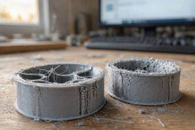
Matte PLA is highly hygroscopic. When it absorbs atmospheric moisture, that trapped water boils inside the 220°C hotend. During a print, these microscopic steam explosions violently disrupt the continuous flow rate, creating random bulging lines that mimic mechanical Z-wobble perfectly.
You must stop storing your filament in the open air or in passive plastic tubs. Invest in a premium, active, heated filament desiccation system like the Sunlu S4. These high-capacity units allow you to actively bake the moisture out of four spools simultaneously at 50°C, feeding the bone-dry filament directly into your extruder via sealed PTFE tubing.
By purchasing an industrial-grade dry box through reputable networks like ShareASale or direct manufacturer portals on Impact, you guarantee that your polymer never touches humid room air. Dry filament flows with absolute volumetric predictability, locking in your highly sensitive extrusion parameters permanently.
3. Upgrade to Authentic Hiwin Linear Rails
If your printer utilizes cheap, generic linear rails or standard rubber V-wheels, you are battling inherent mechanical slop. Budget rails have poorly milled raceways, creating internal grinding micro-vibrations that the software cannot map or cancel out.
To achieve flawless kinematics, you must upgrade to authentic Hiwin MGN9H or MGN12H linear rails. Hiwin is the global gold standard for CNC manufacturing, offering zero-backlash, pre-loaded carriages that glide with microscopic precision. Installing genuine rails eliminates mechanical chatter instantly, resulting in ultra-smooth, band-free outer walls.
[IMAGE PLACEHOLDER: A professional studio shot of an advanced CHT nozzle being installed next to an active filament dryer system + Alt Text: Upgrading your thermal ecosystem to permanently fix 3D print banding and resonance artifacts.]
Quick-Action Preventative Maintenance Checklist
To maintain your flawlessly smooth, band-free walls and protect your hardware investments, implement this strict preventative maintenance protocol before your next major production run:
- Audit Frame Rigidity: Ensure the table or bench your printer sits on is bolted to a wall or features heavy cross-bracing. A swaying table will always override input shaping algorithms.
- Wipe Down Z-Axis Rods: Dust and plastic debris will stick to the grease on your Z-axis lead screws, turning the lubricant into a thick, binding paste. Wipe the screws clean with isopropyl alcohol and re-lubricate every 150 hours of printing.
- Check Extruder Gear Tension: Ensure the spring tension arm on your extruder is tight enough to grip the filament without crushing it. Crushed filament deforms into an oval, causing highly irregular flow rates that look exactly like layer banding.
- Recalibrate After Moving: If you physically pick up and move the printer to a new room or a new table, you must re-run the complete Vibration Compensation diagnostic. The resonant frequency of the machine changes radically based on the density of the surface it is sitting on.
By treating your 3D printer as a high-precision kinematic instrument and eliminating environmental resonance, you will completely eradicate frustrating horizontal artifacts. Secure your frame, calibrate your flow, and start manufacturing with elite, industrial-grade perfection.