9 Expert Ways to Fix 3D Print Layer Shift (Diagnose the “Shift Back” Illusion)
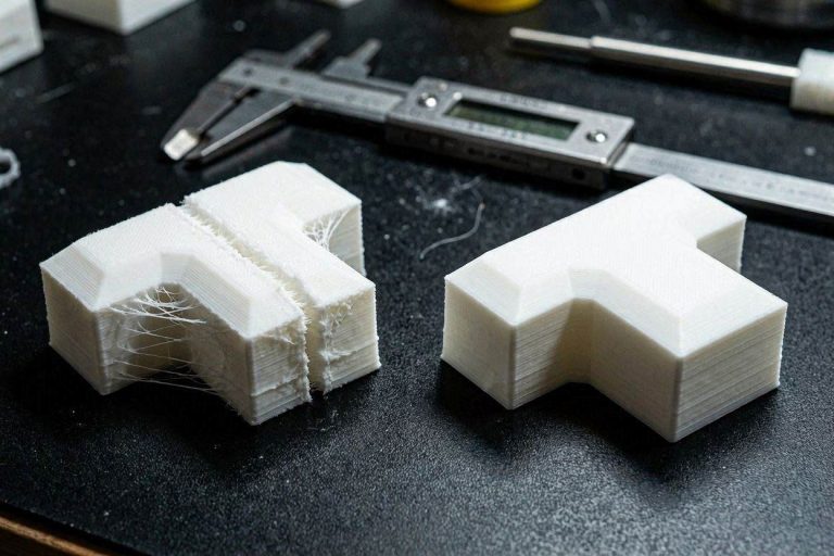
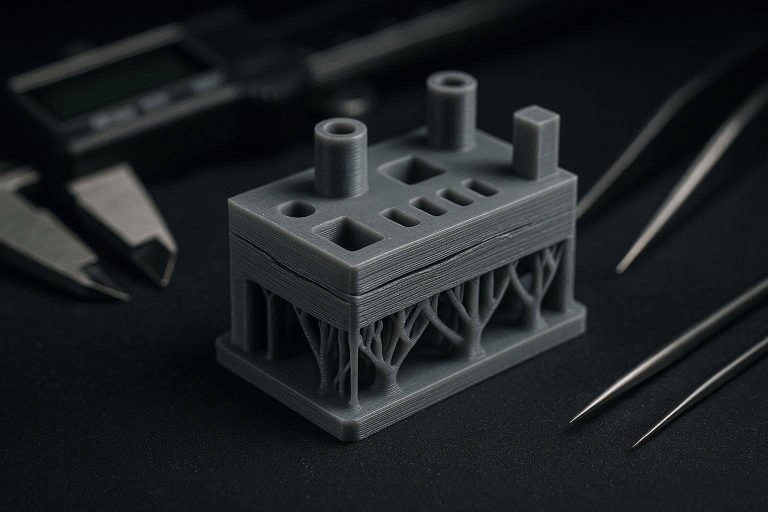
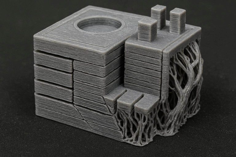
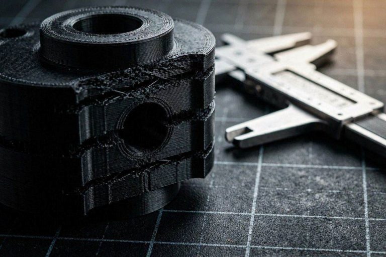
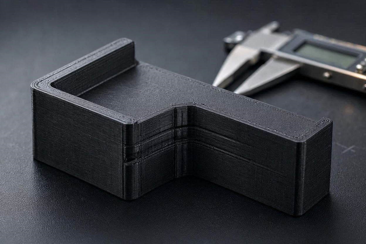
Encountering a severe horizontal displacement halfway through a 15-hour print is one of the most agonizing experiences in additive manufacturing. When you inspect the ruined part, you typically expect to see a classic mechanical failure where the top half of the print is permanently stepped to the left or right. However, many operators are increasingly encountering a bizarre mechanical paradox: the print shifts drastically, prints for an hour, and then miraculously shifts back into perfect alignment.
If your 3D printer appears to temporarily lose its mind and then fix itself, you are not experiencing a standard stepper motor failure. You are witnessing a physical illusion. Modern open-loop stepper motor systems cannot magically correct a dropped coordinate. If you are desperately trying to fix 3D print layer shift artifacts that correct themselves, you must stop looking at your software and start looking at your physical hardware rigidity.
In this deeply technical, exhaustive diagnostic manual, we will deconstruct the exact mechanical kinematics of your 3D printer. We will differentiate between a true dropped step and a physical toolhead deflection. We will explore the physics of tall-part leverage on bed-slinger machines, analyze the dangers of hotend twisting, and provide the exact engineering workflows required to permanently fix 3D print layer shift anomalies.
The “Quick Answer” / Key Takeaways Box
- The Kinematic Paradox: A true layer shift is permanent. If your print shifts and then shifts back to the original alignment, it is a physical illusion caused by loose hardware or a moving model, not a skipped stepper motor.
- The Hotend Twist: The most common cause of the “shift back” illusion is a loose hotend assembly. If the print head can twist left or right under pressure, the nozzle tip coordinates change while the machine thinks it is perfectly still.
- The Leverage Effect: On bed-slinging printers, tall parts act as physical levers. If the base lifts slightly but does not detach, the top of the print leans, creating a false shift.
- Infill Collisions: Using grid infill creates intersecting plastic bumps. High-speed nozzle collisions with these bumps can temporarily deflect the toolhead or knock the magnetic PEI sheet out of alignment.
- True Shift Solutions: If the shift is permanent, you must physically tension your GT2 belts, lubricate your linear rails, and check your stepper motor operating temperatures.
Deconstructing the Kinematics of a Layer Shift
Before you can effectively fix 3D print layer shift issues, you must understand the mathematical logic your machine uses to navigate physical space. The vast majority of desktop 3D printers, including advanced models like the Bambu Lab A1 series, utilize open-loop kinematic systems.
An open-loop system means the printer’s motherboard sends electrical pulses to the stepper motors, commanding them to move a specific distance. However, there are no optical encoders or sensors on the motors to verify that the movement actually occurred. The motherboard simply assumes the motor did exactly what it was told.
When a true layer shift happens, the toolhead encounters a physical obstruction that is stronger than the magnetic holding torque of the stepper motor. The motor is told to move 10 millimeters, but it physically stalls and only moves 5 millimeters.
Why a Skipped Step is Permanent
The motherboard does not know this stall occurred. It still registers the toolhead as having moved the full 10 millimeters. Therefore, every single subsequent G-code command for the rest of the print will be offset by that exact 5-millimeter error. The top half of your print will be permanently shifted.
This absolute law of kinematics is the key to our diagnosis. If your print shifts by 5 millimeters, prints thirty layers, and then shifts back by exactly 5 millimeters to resume perfect alignment with the base, you did not skip a stepper motor step.
It is mathematically and statistically impossible for a 3D printer to randomly skip exactly the same amount of micro-steps in the exact opposite direction to perfectly correct itself. To fix 3D print layer shift illusions of this nature, we must abandon firmware diagnostics and investigate physical hardware deflection.
Step 1: Diagnosing Hotend Deflection and Twisting
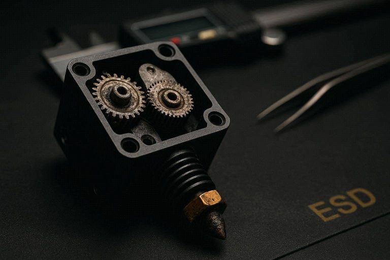
The single most critical diagnostic clue for a “shift back” anomaly is toolhead rigidity. Many modern printers feature quick-swap hotend assemblies. These mechanisms use a series of clips, magnets, or small set screws to hold the heating block and nozzle to the X-axis carriage.
If these retention mechanisms are even slightly loose, the entire hotend can twist on its vertical axis. This is a catastrophic mechanical vulnerability.
The Nozzle Coordinate Shift
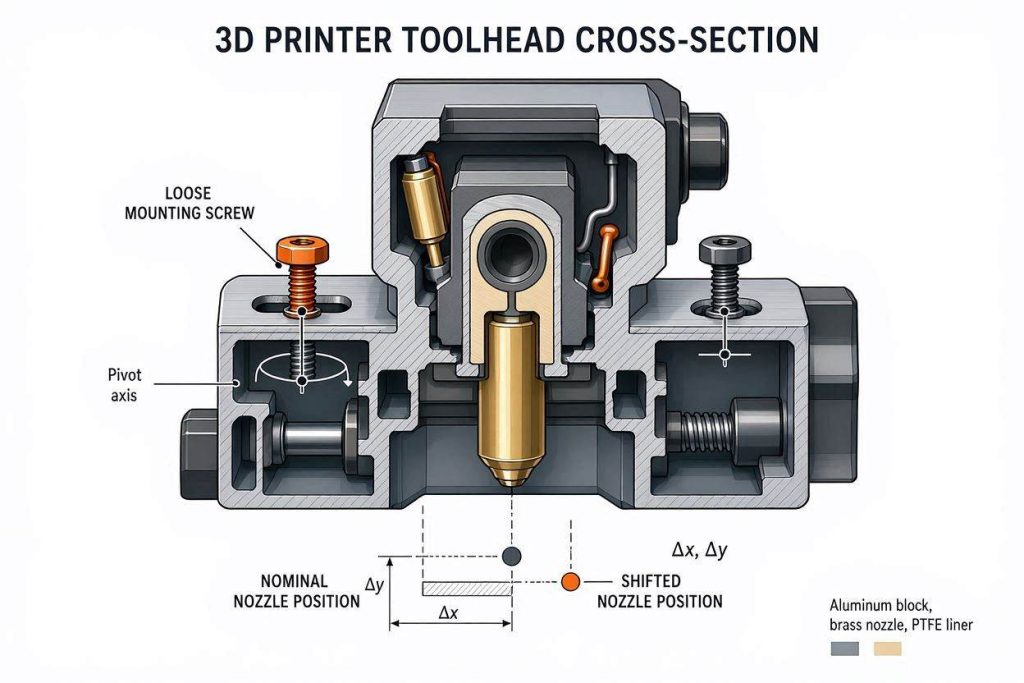
Imagine your toolhead is moving rapidly across the X-axis. The nozzle catches on a slightly over-extruded piece of plastic. The force of this collision does not stall the stepper motor, but it does cause the loose hotend assembly to twist 2 degrees to the left.
Because the nozzle tip is several centimeters below the pivot point, a 2-degree twist at the top translates to a massive 3-millimeter horizontal shift at the nozzle tip. The printer continues to print, but the plastic is now being deposited 3 millimeters to the left of where the motherboard thinks it is.
Thirty layers later, the nozzle catches on another piece of plastic while moving in the opposite direction. The hotend twists back to its original, centered position. The print magically “fixes” itself.
To permanently fix 3D print layer shift illusions, you must power down the printer, grip the cold nozzle with your fingers, and attempt to wiggle it. It should feel like a solid block of concrete. If there is even a fraction of a millimeter of rotational play, you must disassemble the toolhead housing and aggressively tighten the mounting screws securing the hotend to the carriage block.
Step 2: The Bed-Slinger Leverage Effect
If your toolhead is perfectly rigid, the next physical vulnerability lies in the object you are printing. This is especially prevalent on Cartesian bed-slinging architectures, where the heavy Y-axis bed moves forward and backward.
When you print a tall, wide object (like a helmet or a large mechanical enclosure), you are printing a giant physical lever. The base of the lever is attached to your PEI build plate. The tip of the lever is being constantly pushed and pulled by the friction of the nozzle.
Warping as a Kinematic Variable
If your bed adhesion is imperfect, the extreme corners of your large print may begin to warp and curl upward as the plastic cools and shrinks. This curling introduces immense tension.
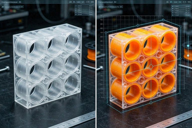
Eventually, the tension overcomes the bed adhesion on one side of the print. The base of the print lifts off the bed by a few millimeters, but the other side remains attached. The entire model physically leans over.
The printer continues to deposit plastic on this leaning model. Because the model is tilted, the new layers are offset horizontally from the base. Several hours later, the weight of the new plastic—or the physical downward pressure of the nozzle—snaps the warped base back down flat against the magnetic build plate. The model stands straight up again, and the new layers return to their original alignment.
To fix 3D print layer shift anomalies caused by model leverage, you must guarantee absolute bed adhesion. Wash your PEI plate with hot water and dish soap, use a liquid adhesive like Magigoo for large footprints, and ensure your ambient room temperature is not causing rapid thermal contraction.
Step 3: Eliminating Grid Infill Collisions
Even with a rigid toolhead and perfect bed adhesion, you can still experience horizontal displacement if your slicer settings are actively fighting your hardware. The most common software-induced mechanical failure is the use of Grid infill.
Grid infill prints intersecting straight lines on the exact same layer. When the nozzle prints a horizontal line, it must plow directly through the semi-molten vertical line it printed seconds earlier.
The Acoustic Shockwave
At low speeds, the hot nozzle easily melts through these intersections. At high speeds (300+ mm/s), the nozzle acts like a physical battering ram. Every time it crosses a grid intersection, it creates a microscopic collision.
These rapid-fire collisions create an acoustic shockwave that travels up the toolhead and down through the printed part. This violent stuttering can cause two distinct failures that look like layer shifts:
- Magnetic Plate Slippage: The continuous hammering can physically push your flexible spring-steel PEI sheet across the magnetic base. The plate slides a few millimeters, shifting the print. Later, a collision in the opposite direction slides the plate back.
- Stepper Motor Micro-Stalls: The combined resistance of thousands of grid intersections can temporarily overcome the motor torque, causing a true shift.
To immediately fix 3D print layer shift risks associated with internal geometry, open your slicer and permanently abandon Grid infill. Change your default infill pattern to Gyroid or Cross Hatch. These modern patterns never cross their own paths on the same layer, ensuring the nozzle glides effortlessly through the internal voids without a single mechanical collision.
[INTERNAL LINK: Placeholder for “How to Optimize Infill Patterns for High-Speed CoreXY 3D Printers”]
Step 4: True Layer Shifts – GT2 Belt Tensioning
If you have ruled out toolhead deflection and model rocking, and your print shifts permanently without ever shifting back, you have a true, open-loop kinematic failure. The most frequent cause of a permanent skipped step is improper timing belt tension.
3D printers rely on fiberglass-reinforced rubber GT2 timing belts to translate rotational motor movement into linear toolhead movement.
- Under-Tensioned Belts: If the belt is too loose, the rubber teeth will literally jump over the metal teeth of the stepper motor pulley during a high-acceleration maneuver. The motor turns, but the belt stays still.
- Over-Tensioned Belts: If the belt is too tight, it places immense lateral stress on the stepper motor shaft. The motor bearings bind, and the motor lacks the rotational torque to overcome this artificial friction, causing it to stall and drop steps.
Acoustic Belt Calibration
You cannot tension belts reliably by “feel.” To properly fix 3D print layer shift kinematics, you must use acoustic frequency tuning.
Move your toolhead to the center of the gantry. Download a sonic frequency analyzer app (like Spectroid) on your smartphone. Pluck the longest exposed run of your X or Y axis belt like a guitar string.
While ideal frequencies vary by machine manufacturer, a standard GT2 belt spanning roughly 150mm should emit a bass note hovering around 90Hz to 110Hz. If your belt plucks with a dull, low 40Hz thud, it is dangerously loose. If it pings at 180Hz, it is stretching the motor shaft and must be slackened immediately.
Step 5: Lubrication and Linear Rail Binding
If your belts are perfectly tensioned but the toolhead still drops steps, you must audit your linear motion guides. High-speed printers utilize hardened steel linear rails and carriage blocks packed with microscopic ball bearings.
These systems are engineered for zero-friction movement, but they require strict maintenance. Over hundreds of printing hours, microscopic strands of plastic, airborne dust, and pet hair are drawn to the oily rails.
The Friction Threshold
This debris mixes with the factory grease, turning it into a thick, abrasive paste. When the toolhead attempts to glide over this paste, the physical resistance spikes. If this resistance spike coincides with a high-speed diagonal travel move, the stepper motor will instantly stall, permanently ruining the print.
To fix 3D print layer shift failures caused by rail binding, you must implement a rigorous cleaning protocol.
- Wipe the steel rails down entirely with a lint-free cloth soaked in 99% isopropyl alcohol.
- Once dry, apply a specialized PTFE-based synthetic grease (like Super Lube 21030) directly to the tracks.
- Manually push the toolhead back and forth across the rails twenty times to work the fresh grease deep into the internal ball bearing raceways. The movement should feel flawlessly smooth, with zero hesitation or “gritty” feedback.
Step 6: Stepper Motor Thermal Overload
Stepper motors generate immense heat when operating at high velocities for prolonged periods. The electrical current required to hold a heavy toolhead in place causes the internal coils to act as miniature heaters.
If your 3D printer is housed inside a warm enclosure to print materials like ABS or ASA, the ambient chamber temperature can easily exceed 50°C.
The Magnetic Drop-Off
Stepper motors rely on internal permanent magnets to hold their positions. As the physical temperature of a neodymium magnet increases, its magnetic flux density drops. If a stepper motor reaches 80°C or 90°C, it physically loses its holding torque.
A motor that operates flawlessly at room temperature will become mathematically weak when overheated. It will begin dropping steps under normal loads, causing catastrophic layer shifts hours into a complex print.
To definitively fix 3D print layer shift issues related to thermal degradation, you must check your motor temperatures. During a long print, touch the back of your X and Y stepper motors. If they are too hot to comfortably hold your finger against for more than three seconds, they are overheating. You must lower the ambient chamber temperature, reduce your printing speeds, or install active heatsinks and cooling fans directly onto the metal motor housings.
Official Klipper Documentation on Stepper Motor TMC Driver Current and Thermal Limits]
Step 7: Pulley Set Screw Slippage
The most insidious and difficult-to-diagnose cause of a permanent layer shift is a slipping pulley. The metal toothed pulley that drives your GT2 belt is not permanently welded to the stepper motor shaft. It is held in place by one or two tiny, microscopic “grub screws” (set screws).
Stepper motor shafts have a flat side machined into them. The primary grub screw must be driven directly into this flat face to prevent rotation.
The Micro-Slip Failure
Due to the continuous, violent vibrations of high-speed printing, these tiny grub screws can slowly back out over time. When the screw loosens, the motor shaft turns, but the pulley slips around the shaft before catching again.
This causes the toolhead to lag behind the motor’s intended position, resulting in a permanent layer shift that looks exactly like a skipped belt tooth.
To ensure you absolutely fix 3D print layer shift hardware vulnerabilities, you must power down the printer and locate every drive pulley on your X and Y motors. Use a high-quality hex wrench to back the screws out completely. Apply a single drop of blue thread-locker (Loctite 242) to the threads, ensure the primary screw is perfectly aligned with the flat side of the motor shaft, and torque it down aggressively.
Step 8: The Permanent Fix: Quality Kinematic Upgrades
While tightening screws and abandoning Grid infill will resolve the vast majority of shifting artifacts, relying on budget-tier factory hardware leaves your manufacturing process vulnerable. If you are operating a print farm and cannot afford a single failed part, software tuning is insufficient. You must upgrade your kinematic foundation with industrial-grade, high-ticket assets.
1. Upgrade to Authentic Hiwin Linear Rails
The generic linear rails that ship on budget 3D printers utilize unpolished bearings and poorly milled raceways. This results in the exact micro-binding that causes sudden, unpredictable stepper motor stalls.
To achieve flawless, zero-friction kinematics, you must upgrade your X and Y axes to authentic Hiwin MGN12H or MGN9H linear rails. Hiwin is the global gold standard for CNC manufacturing, offering pre-loaded carriages that glide with microscopic fluidity. You can source genuine Hiwin components directly from authorized industrial distributors through the MatterHackers or ShareASale affiliate networks. Installing genuine rails entirely eliminates Y-axis binding, protecting your prints from permanent coordinate shifts.
2. Premium Garolite (G10) Build Plates
We established that the “shift back” illusion is often caused by tall models warping and rocking on the build plate. Flexible magnetic PEI sheets are fantastic for PLA, but they struggle to hold the extreme thermal contraction forces of ABS, Nylon, or large PETG parts.
To achieve an unbreakable foundation, upgrade to a rigid, 3mm thick G10 (FR4 Garolite) build plate. Garolite is an industrial fiberglass composite that offers terrifyingly strong adhesion while hot, completely preventing the corners of your model from lifting and acting as a lever against your nozzle. Sourcing a custom-cut G10 plate through specialist vendors on PartnerStack guarantees your model remains mathematically flat from the first layer to the last.
3. Active Heated Filament Desiccation
If you are suffering from nozzle collisions that twist your toolhead, your filament is likely over-extruding. Hygroscopic filaments absorb moisture, which boils in the hotend, causing massive volumetric pressure surges that leave giant blobs on your print. The nozzle then crashes into these blobs.
You must stop storing your filament in plastic tubs. Invest in an active, heated filament dryer like the Sunlu S4. This allows you to bake four spools simultaneously at 65°C, feeding bone-dry filament directly into your extruder. Dry filament flows with absolute predictability, eliminating the erratic blobs that cause mechanical collisions. Premium active dryers can be sourced directly through manufacturer programs on the Impact affiliate network.
[IMAGE PLACEHOLDER: A professional studio photograph of genuine Hiwin linear rails being installed onto a 3D printer gantry next to a premium G10 build plate + Alt Text: Upgrading your kinematic hardware to permanently fix 3D print layer shift failures.]
Step 9: Quick-Action Preventative Maintenance Checklist
To maintain your mathematically perfect kinematics and protect your hardware investments, implement this strict preventative maintenance protocol before your next major production run:
- Audit Toolhead Rigidity: Every 50 hours of printing, physically grip your cold nozzle and attempt to wiggle it. If there is any rotational play, tear down the shroud and tighten the hotend mounting screws to prevent the “shift back” illusion.
- Wipe Down Linear Rails: Do not let dust accumulate on your precision steel tracks. Wipe them down weekly with a clean microfiber cloth to prevent abrasive paste from forming and binding the carriage blocks.
- Check Belt Dust: Shine a flashlight onto your stepper motor pulleys. If you see a buildup of black rubber dust, your belts are rubbing against the flanges and shredding themselves. This means your gantry is out of square.
- Monitor Enclosure Temperatures: If you are printing inside a sealed chamber, ensure your ambient temperature does not exceed 45°C unless your stepper motors are actively water-cooled. Overheated motors will lose magnetic holding torque and drop steps.
By treating your 3D printer as a high-precision CNC asset and rejecting superficial software band-aids, you can systematically eliminate every variable causing your layer lines to shift. Lock down your hotend, tension your belts acoustically, and start manufacturing with elite, industrial-grade reliability.