9 Proven Strategies to Fix 3D Print Visible Line Transitions (Stop Bulging Artifacts!)
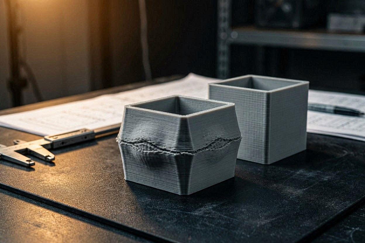
Nothing is more frustrating than pulling a seemingly perfect model off your build plate, only to discover a harsh, tactile ridge running horizontally across the entire perimeter. If you are trying to fix 3D print visible line defects that appear exactly where a solid base transitions into hollow walls, you are experiencing one of the most notorious thermodynamic anomalies in additive manufacturing. This specific defect is often referred to in engineering circles as the “Benchy Hull Line,” and it plagues everyone from beginners to advanced print farm operators.
The sudden appearance of this bulging artifact is rarely caused by loose belts or a bent Z-axis lead screw. Instead, it is a complex failure of internal nozzle pressure, thermal contraction rates, and volumetric flow. When your machine transitions from printing slow, massive solid layers to rapid, thin walls, the physical state of the extruded polymer changes violently. To eradicate this artifact, you must look beyond basic leveling and dive into the advanced settings of your slicing software.
In this comprehensive, deeply technical diagnostic manual, we will deconstruct the exact physics behind this sudden horizontal bulge. We will explore how to manipulate your slicer’s speed algorithms, restructure your wall-printing sequences, and even alter your CAD geometry to achieve perfectly smooth outer perimeters. By the end of this guide, you will have the exact workflows required to permanently fix 3D print visible line defects and restore your manufacturing quality to flawless tolerances.
The “Quick Answer” / Key Takeaways Box
- The Root Cause: The visible line is a thermal and pressure-based artifact. It occurs when a solid infill base transitions abruptly into a thin, hollow wall, causing a massive shift in layer cooling times.
- Print Order Matters: Always set your slicer to print “Outer Walls, Inner Walls, Infill” (Outer/Inner). This ensures the visible perimeter is laid down before internal infill pressure can push the plastic outward.
- Minimum Layer Time: Slowing down the rapid wall layers to match the duration of the solid base layers keeps the thermal mass consistent, preventing differential shrinkage.
- Geometric Fillets: If you are designing the part, add an internal fillet or chamfer to the bottom floor. This creates a gradual transition over multiple layers rather than a sudden, one-layer structural shock.
- The “Slot” Relief Method: Modeling a small, intentional horizontal slot or groove exactly at the transition point physically breaks the tension and hides the bulging artifact entirely.
The Thermodynamics Behind the Visible Line Artifact
Before you can successfully implement a fix 3D print visible line strategy, you must understand the microscopic physics occurring at the tip of your 0.4mm nozzle. 3D printing is an exercise in controlled thermal degradation.
When your machine is printing the solid bottom base of a container, the toolhead is extruding a massive volume of plastic. This solid block of 100% infill retains a significant amount of thermal mass. Because these layers take a long time to complete, the part cooling fan has ample time to blow across the surface.
However, the moment the printer finishes the solid floor and begins printing the thin vertical walls, the dynamic changes instantly. The hollow wall layers take a fraction of the time to print compared to the solid base.
Differential Cooling and Shrinkage
Thermoplastics like PLA, PETG, and ABS shrink as they cool from their molten state back to room temperature. This is governed by their Coefficient of Thermal Expansion (CTE).
When the print transitions to the rapid wall layers, these new layers cool and freeze almost instantly due to their low mass. Meanwhile, the dense solid base beneath them is still slowly radiating heat. This temperature differential causes the layers to contract at different rates. The cooler, faster layers pull against the warmer, slower layers, forcing the interface point to bow and bulge outward.
This results in a prominent, tactile line across the exact Z-height where the solid infill stopped.
Internal Hotend Pressure Dynamics
The second mechanical factor is volumetric flow pressure. When the extruder is laying down dense solid infill, the internal pressure inside the hotend is pushed to its absolute maximum.
When the toolhead finishes that solid layer and immediately steps up to print a thin outer wall, the internal pressure has not fully dissipated. The nozzle is still over-pressurized. As it rounds the perimeter of the new hollow wall, it accidentally extrudes slightly more plastic than the slicer commanded.
This excess plastic has nowhere to go but outward, creating the distinct horizontal ridge. To achieve a fix 3D print visible line solution, we must algorithmically manage both the thermal mass and this internal pressure spike.
[IMAGE PLACEHOLDER: A cross-section diagram of a 3D printed box showing internal hotend pressure surging at the transition point between solid infill and hollow walls + Alt Text: An engineering diagram explaining the volumetric pressure surge that requires you to fix 3D print visible line defects.]
Step-by-Step Slicer Settings for a Flawless Transition
Modern slicing engines like OrcaSlicer and Bambu Studio offer highly granular controls to manipulate toolhead kinematics. By forcing the printer to alter its behavior at the exact transition point, you can mitigate the sudden thermal shock.
1. Optimize the Wall Printing Sequence
The single most effective software adjustment you can make is changing your wall generation order. By default, many slicers are set to print “Inner/Outer.” This means the toolhead prints the inside of the wall first, followed by the visible outer shell.
While this is great for extreme overhangs, it is terrible for dimensional accuracy. If the internal solid infill is slightly over-extruded due to pressure buildup, printing the inner wall first forces all that excess plastic outward. When the outer wall is finally printed, it is pushed over the edge by the swollen plastic behind it.
The Solution: Navigate to your slicer’s Quality or Walls tab. Change the wall ordering to Outer/Inner/Infill. By printing the outermost perimeter first, the toolhead lays down the visible shell against empty air, guaranteeing absolute dimensional accuracy. Any over-extrusion or pressure surging from the internal infill is trapped inside the model, completely invisible to the naked eye.
2. Enforcing Minimum Layer Times
If the artifact is caused by rapid cooling differences, we must force the fast wall layers to print at the same speed as the slow base layers.
The Solution: Navigate to the Cooling tab in your slicer settings. Locate the parameter titled Minimum Layer Time or Slow Down for Better Cooling. If your solid base layers take 30 seconds to print, set your minimum layer time to 25 or 30 seconds. When the printer reaches the hollow walls (which might naturally only take 8 seconds), the slicer will artificially throttle the toolhead speed down to a crawl.
This ensures that the walls take the exact same amount of time to complete as the base. The thermal mass dissipates at a uniform rate, eliminating the differential shrinkage that causes the prominent ridge.
3. Modulating Volumetric Flow with Modifier Meshes
Sometimes, minimum layer time is not enough if the geometry change is excessively dramatic. Going from a 100% solid brick to a 1.2mm thick wall is a massive kinetic jump.
If global settings fail, you must utilize modifier meshes.
The Solution:
- Right-click your model in the slicer and add a Modifier Box.
- Scale and position this box so it only intersects the specific Z-height where the solid base meets the wall.
- Assign custom settings to this specific modifier mesh. Drop the Outer Wall Speed by 50% and reduce the Extrusion Multiplier (Flow Rate) by 2%.
By manually starving the hotend of plastic at the exact layer transition, you counteract the pressure surge. The resulting perimeter will lay down perfectly flush with the rest of the model.
[VIDEO PLACEHOLDER: A screen-recording tutorial demonstrating how to apply a modifier mesh in OrcaSlicer to reduce wall speed at a specific Z-height.]
Modifying CAD Geometry to Eliminate the Artifact
If you are the original designer of the STL file, the absolute best way to fix 3D print visible line defects is to engineer them out of the CAD geometry before the file ever reaches the slicer. Software tricks are bandaids; geometric optimization is a cure.
The Internal Fillet Strategy
The artifact occurs because the transition from a solid floor to a vertical wall happens instantly, over the span of a single 0.2mm layer. This creates a severe, 90-degree internal shelf.
You can entirely dissipate this thermal stress by adding an internal fillet or chamfer to the bottom of the container.
The Execution: Open your CAD software (Fusion 360, SolidWorks, or Onshape). Select the internal bottom edge where the floor meets the wall. Apply a 2mm or 3mm fillet. When this modified geometry is sliced, the printer no longer transitions from 100% solid to 10% wall in one layer. Instead, it slowly steps up the transition over 15 to 20 layers. The thermal mass smoothly tapers off, and the internal pressure dissipates gradually. The outside of your model will remain flawlessly straight.
The Mechanical “Slot” Relief Method
In highly specific engineering scenarios, you may not be able to add an internal fillet due to physical clearance requirements for internal components. In this case, you can use the “Slot Method.”
The Execution: Instead of trying to fight the thermal contraction, you intentionally hide it. In your CAD software, cut a tiny horizontal groove or slot (0.5mm deep and 1mm tall) into the outside of the model, exactly at the Z-height where the solid floor ends.
This serves two purposes. First, the missing material acts as a mechanical stress-relief joint, allowing the plastic to contract without pulling the layers above it. Second, the visual shadow created by the slot completely camouflages any micro-bulging that does occur. It transforms an ugly defect into an intentional, aesthetic design feature.
Autodesk Fusion 360 Official Documentation on Applying Fillets and Chamfers for Stress Relief
Advanced Thermal Diagnostics: Ambient Environment
If you have altered your slicer settings and modified your CAD files, yet you still cannot fix 3D print visible line artifacts, the variable lies outside of your machine.
FDM 3D printing relies heavily on ambient environmental stability. If your printer is sitting on a desk in a drafty room, underneath an HVAC vent, or near a cold window, the thermal dynamics of your plastic are being compromised.
The Danger of Uneven Drafts
When a cold draft of air hits a 3D print, it forces the polymer to cross its glass transition threshold prematurely. If the draft hits one side of the print harder than the other, the shrinkage becomes asymmetrical.
The heavy solid base of your print resists this draft due to its high thermal density. The thin vertical walls, however, are instantly chilled by the ambient air. This exacerbates the exact differential cooling sequence we discussed earlier.
To achieve industrial-grade dimensional accuracy, you must eliminate ambient drafts entirely.
[INTERNAL LINK: Placeholder for “How to Calibrate PID Tuning for Maximum Hotend Thermal Stability”]
The Permanent Fix (Premium Hardware Monetization)
If you are running a high-volume commercial print farm, you cannot afford to waste hours tweaking custom modifier meshes for every single design. To permanently fix 3D print visible line issues across all materials, you must upgrade the thermodynamic ecosystem of your hardware.
Professional operators eliminate thermal shrinkage and pressure surging by investing in high-ticket upgrades that enforce absolute environmental control.
1. Active Thermal Enclosures
You cannot control thermal contraction if you cannot control the ambient air. Relying on an open-frame bed slinger for dimensionally accurate, flat walls is a losing battle. You must upgrade to a premium, sealed 3D printer enclosure.
High-end enclosures trap the radiant heat from the build plate, maintaining a steady 40°C to 50°C ambient chamber temperature. This prevents the thin outer walls from freezing instantly, ensuring they shrink at the exact same slow rate as the solid base. You can source professional-grade acrylic and aluminum enclosures tailored for specific machines via the MatterHackers affiliate portal.
2. High-Flow CHT (Core Heating Technology) Nozzles
The pressure surge that causes the horizontal bulge is a direct result of poor melt-zone efficiency. Standard brass nozzles melt filament unevenly, leaving the core of the plastic semi-solid. This requires massive extruder pressure to force the plastic out.
Upgrading to a premium CHT nozzle splits the filament into three internal flow paths, drastically increasing the heated surface area. The plastic melts homogenously, becoming a highly fluid liquid that requires almost zero back-pressure to extrude. When the transition from solid infill to thin walls occurs, a CHT nozzle exhibits zero pressure surging, eliminating the bulge. You can source elite aftermarket nozzles through ShareASale partners like Bondtech.
3. Dimensionally Stable Engineering Polymers
Not all PLA is manufactured to the same chemical standard. Cheap, white-label filament utilizes low-grade resins that suffer from massive thermal expansion coefficients. If you are struggling with visible layer lines and unpredictable shrinkage, you must upgrade your raw materials.
Switching to premium, engineering-grade filament brands like Polymaker or Prusament guarantees strict chemical consistency and a massive reduction in warping behavior. Sourcing premium materials directly through their official affiliate networks guarantees your hardware is fed the optimal polymer for structural accuracy.
Quick-Action Preventative Maintenance Checklist
To ensure your machine remains highly accurate and to permanently eradicate the solid-to-wall transition bulge, implement this strict preventative maintenance protocol before your next production run:
- Lock in the Print Sequence: Always verify your slicer’s wall generator is set strictly to Outer/Inner/Infill. Never print the internal pressure zones first.
- Audit Cooling Fans: Inspect your part-cooling radial fans. If the fan ducts are misaligned, they may be blasting the print unevenly, exacerbating thermal shrinkage on one side of the artifact.
- Calibrate Volumetric Flow: Run a maximum volumetric flow rate test for every new spool of filament. If you are pushing the plastic faster than the hotend can melt it, pressure surging at transition points is inevitable.
- Implement Minimum Layer Times: Set a hard floor of 20 to 25 seconds per layer in your filament cooling settings to ensure thermal mass dissipates evenly across drastic geometry changes.
- Check Z-Axis Lubrication: While thermal physics cause the hull line, a dry or binding Z-axis lead screw will make the artifact appear 10x worse. Wipe down the lead screws and apply a fresh coat of PTFE synthetic grease every 150 print hours.
By treating your 3D printer as an exercise in advanced thermodynamics and implementing these strict slicer and CAD workflows, you will completely eliminate the frustrating visible transition lines. Stop accepting flawed geometry and start manufacturing with elite, industrial-grade precision.
A brilliant article! I had exactly that problem the other day and have already tried out a few of the tips from here. Unfortunately, the minimum layer time is a bit of an issue, as it slows my print down considerably. I’m actually thinking of going back to my model now. But incorporating this sort of safety measure isn’t actually that straightforward with my design.
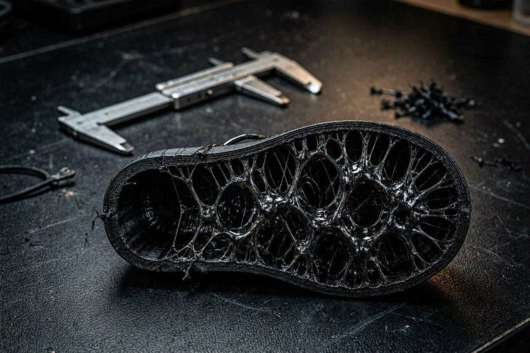
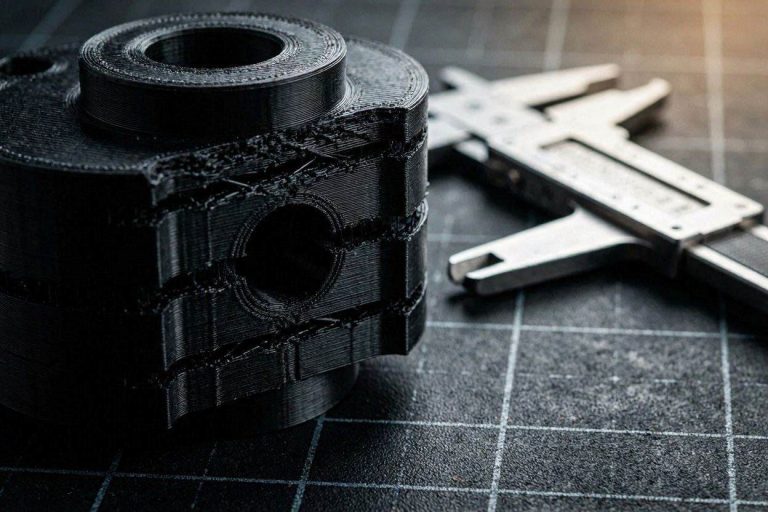
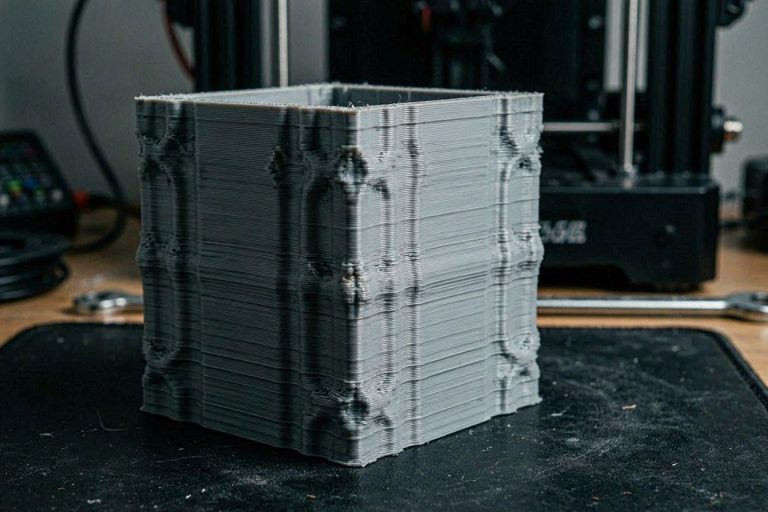
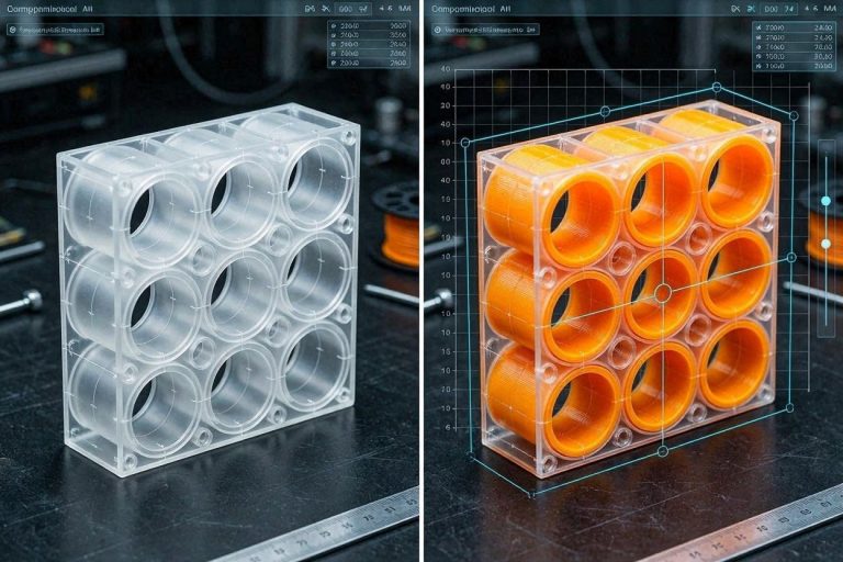
Just so you understand: in my case, it’s a sort of 5 mm thick wall with loads of Swiss cheese-style holes. The layers with the holes are, unsurprisingly, printed more slowly, whilst the printer can print quickly in between them. So, wherever there are holes and the transition to the solid wall without holes occurs, these tiger stripes appear.
Anyway, many thanks for your effort. I would have appreciated a few pictures. Thank you very much.