7 Powerful Steps to Fix 3D Print Rough Top Layer Defects in 2026 (Stop Over-Extrusion!)
Pulling a completed model off the build plate only to discover a scarred, messy, and ridged top surface is incredibly frustrating. You flip the part over, and the bottom layer is as smooth as glass, yet the top looks like a plowed field. If you are desperately trying to fix 3D print rough top layer defects, you are dealing with a classic case of volumetric over-extrusion and pressure imbalance.
Many operators assume that if they drop their flow rate to 95%, their over-extrusion problems will disappear. However, when you are pushing thick 0.44mm layers through a 0.6mm nozzle at 60 mm/s, the thermodynamic pressure inside your hotend changes completely. You cannot rely on default slicer presets to generate perfectly flat top shells under these heavy volumetric parameters.
In this highly technical, comprehensive diagnostic manual, we will break down the exact physics of top-layer scarring. We will explore how to perfectly calibrate your extrusion multiplier, dial in your pressure advance, and deploy advanced top-surface ironing techniques. By the end of this guide, you will have the exact engineering workflows required to permanently fix 3D print rough top layer anomalies and achieve injection-molded quality finishes.
The “Quick Answer” / Key Takeaways Box
- The Root Cause: A rough, scarred top layer is almost exclusively caused by over-extrusion. The nozzle drags through the excess plastic, carving physical ridges into the surface.
- The Bottom Layer Illusion: The bottom looks perfectly smooth because the plastic is physically “smushed” against a flat glass or PEI bed. The top layer prints in open air, exposing true flow rate errors.
- Calibrate Flow Rate: A default 95% flow rate may still be too high for your specific brand of PLA. You must run a hollow cube flow calibration test with digital calipers.
- Delay Ironing: Do not enable slicer ironing settings until your baseline extrusion flow is flawless, or you will simply bake the excess plastic into worse ridges.
- Tune Pressure Advance: Sharp, raised blobs at the edges of the top layer indicate that your pressure advance (Linear Advance) is improperly calibrated for a 0.6mm nozzle.
The Thermodynamics and Physics of Top Layer Scarring
Before making blind adjustments in your slicer, you must understand the physical mechanics of why your printer is tearing up its own work. Fused Deposition Modeling (FDM) relies on strict mathematical calculations to predict how much plastic should exit the nozzle.
When you ask your slicer to lay down a solid top layer, it calculates the exact volume of plastic required to fill the gaps between the perimeter walls. If your extrusion multiplier (flow rate) is even 2% too high, the hotend will extrude a microscopic amount of excess plastic on every single pass.
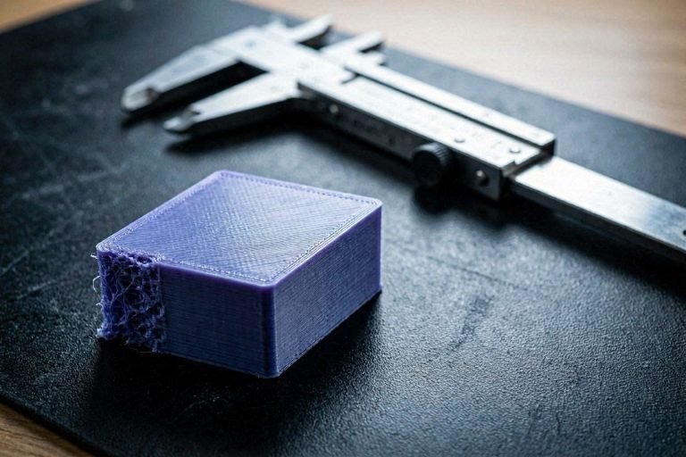
Because the infill below the top layer is solid, this excess plastic has nowhere to go but up. As the nozzle makes its next pass, the physical brass or steel tip acts like a snowplow, dragging through the elevated, cooled plastic from the previous line. This creates the deep, ugly ridges and scarring that ruin your dimensional accuracy.
The 0.6mm Nozzle and Thick Layer Dynamics
In the specific scenario of using a 0.6mm nozzle with a 0.44mm layer height at 60 mm/s, you are pushing the volumetric limits of a standard hotend.
Let us do the math: $0.6 \text{ mm (width)} \times 0.44 \text{ mm (height)} \times 60 \text{ mm/s (speed)} = 15.84 \text{ mm}^3\text{/s}$.
A flow rate of 15.84 mm³/s is exceptionally high for standard PLA printed at 205°C. At this temperature, the core of the filament may not be melting completely, acting as a highly viscous fluid. This creates massive back-pressure inside the hotend. When the toolhead slows down to fill in the dense top layers, this trapped pressure surges out uncontrollably, causing massive over-extrusion.
To achieve a true fix 3D print rough top layer solution, we must systematically balance this pressure.
[IMAGE PLACEHOLDER: A technical cross-section diagram showing a 3D printer nozzle plowing through over-extruded plastic on a top layer + Alt Text: An engineering diagram explaining why over-extrusion requires you to fix 3D print rough top layer defects.]
Step 1: Precision Extrusion Multiplier (Flow Rate) Calibration
You cannot fix top layer scarring without establishing a flawless baseline flow. Guessing at a 95% flow rate is insufficient because every single brand, color, and batch of filament possesses a unique chemical viscosity. You must calibrate the extrusion multiplier mathematically.
The Hollow Wall Cube Test
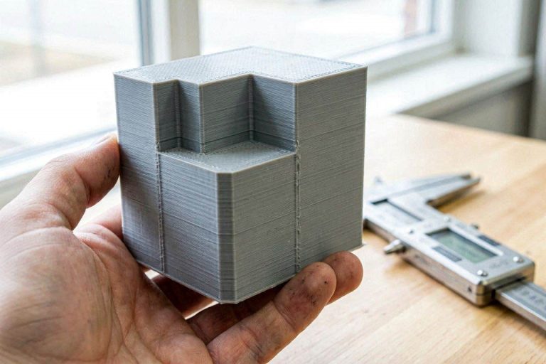
To determine your exact flow rate, you must print a test object that allows you to measure the physical wall thickness without infill interference.
- Open your slicer and generate a simple 20mm x 20mm x 20mm cube.
- Set the Top Layers and Bottom Layers to 0.
- Set the Infill to 0%.
- Set the Wall Line Count to exactly 2.
- If you are using a 0.6mm nozzle, your expected wall thickness should be precisely 1.2mm (0.6mm x 2).
Executing the Calculation
Print the hollow cube at your current 95% flow setting and 205°C. Once the print is finished, let it cool completely.
Take a pair of high-quality digital calipers and measure the thickness of the top edge of the walls. Take measurements on all four sides and average them. If your measured thickness is 1.28mm, you are drastically over-extruding.
Use this universal flow calibration formula:
$New Flow = (Expected Thickness / Measured Thickness) \times Current Flow$
Example: $(1.20 / 1.28) \times 0.95 = 0.89$
In this scenario, your new flow rate should be 89%. Input this new value into your filament profile. This mathematical adjustment is the single most critical step to fix 3D print rough top layer anomalies.
Step 2: Optimizing the Layer Height to Nozzle Ratio
Pushing a 0.44mm layer height through a 0.6mm nozzle is bordering on the absolute physical limits of extrusion geometry. As a general rule of fluid dynamics in 3D printing, your layer height should never exceed 75% of your nozzle diameter.
A 0.44mm layer height is exactly 73.3% of a 0.6mm nozzle. While technically possible, printing this thick severely rounds the edges of the extruded plastic lines. When the slicer attempts to pack these highly rounded lines tightly together to form a flat top shell, the rounded edges overlap and bulge upward.
The Micro-Stepping Adjustment
To reduce the physical bulging and achieve a flatter top shell, you must drop the layer height slightly.
Reduce your global layer height to 0.32mm or 0.36mm. This forces the plastic to spread out flatter against the layer below it, resulting in a more rectangular line profile rather than a circular one. A flatter line profile overlaps much more smoothly, drastically reducing the plow-effect of the nozzle and helping to instantly fix 3D print rough top layer scarring.
[INTERNAL LINK: Placeholder for “How to Calibrate E-Steps on a Direct Drive Extruder”]
Step 3: Dialing in Pressure Advance (Linear Advance)
If your overall top surface looks relatively smooth, but the edges of the top layer (where the toolhead changes direction) feature sharp, raised blobs, your issue is kinematic latency.
Molten plastic behaves like a compressed spring inside your hotend. When your toolhead travels across a long top surface and suddenly decelerates to reach the perimeter wall, the extruder motor stops instantly. However, the compressed plastic inside the nozzle continues to ooze out, depositing a massive blob right at the edge.
Implementing Pressure Compensation
Pressure Advance (Klipper) or Linear Advance (Marlin) is an algorithmic firmware feature designed to predict and neutralize this pressure surge. It commands the extruder motor to briefly reverse (pull back) fractions of a second before the toolhead decelerates.
Because you are using a larger 0.6mm nozzle, your internal hotend pressure drops much faster than it would on a 0.4mm nozzle. Your current Pressure Advance values are likely over-compensating or under-compensating for this massive orifice.
You must run a built-in Pressure Advance Pattern Test in your slicer (like OrcaSlicer or PrusaSlicer) specifically for your 0.6mm profile. By finding the perfect K-value, the toolhead will deposit exactly the right amount of plastic at the corners, keeping the top layer edges perfectly flush with the inner surface.
Step 4: The Danger of “Pillowing” (Top Shell Support)
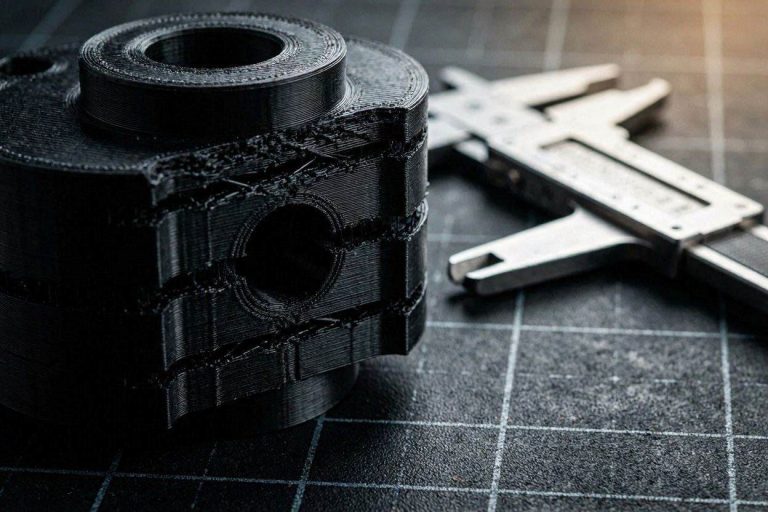
Sometimes, what appears to be an over-extrusion scar is actually a structural collapse known as “pillowing.” This occurs when your top layers are bridging over too sparse of an infill pattern.
You mentioned you are utilizing 4 top layers at a 0.44mm height. While this provides a thick roof, the 205°C molten plastic sags heavily into the empty voids of the infill on the very first top layer. The second layer sags into the depression of the first. By the time the fourth layer prints, the surface is wildly uneven, filled with bumps and divots that the nozzle scrapes against.
Reinforcing the Sub-Structure
To fix 3D print rough top layer pillowing, you must alter your internal support geometry.
- Increase Infill Density: Bump your sparse infill up to at least 15% or 20% to provide a tighter supporting grid for the solid roof.
- Change Infill Pattern: Switch to a structural infill like Gyroid or Cubic. These 3D patterns provide highly uniform vertical support, preventing the top layers from sagging into large rectangular voids.
- Ensure Proper Cooling: Ensure your part-cooling radial fan is running at 100% capacity during the top layers. The plastic must freeze instantly as it bridges the infill gaps to remain perfectly flat.
[VIDEO PLACEHOLDER: A macro video demonstrating the visual difference between top layer pillowing and top layer over-extrusion scarring.]
Step 5: Mastering Top Surface Ironing Settings
Once you have completely dialed in your flow rate, reduced your layer height for better overlap, and secured your infill sub-structure, you can utilize the ultimate finishing tool: Ironing.
Ironing is a slicer feature where the toolhead makes one final pass over the completed top layer. It extrudes a microscopic amount of plastic while the hot nozzle physically melts and smooths out the microscopic ridges left behind by the standard print lines.
Do Not Use Default Ironing Presets
If you turn ironing on while you are still over-extruding, you will make the problem infinitely worse. The nozzle will simply push the excess plastic into massive, ugly waves.
To achieve a mirror-like finish with a 0.6mm nozzle, use these custom ironing parameters:
- Ironing Pattern: Monotonic. This forces the toolhead to always iron in the same direction, preventing weird light-reflecting artifacts where the toolhead changed paths.
- Ironing Speed: Slow it down to 20 mm/s or 30 mm/s. The brass nozzle needs time to physically transfer heat into the plastic to melt the high spots.
- Ironing Flow Rate: Set this to 10% or 12%. You only want a tiny trickle of plastic to fill in the microscopic valleys.
- Line Spacing: Set this tightly to 0.15mm. The closer the passes, the smoother the final melt.
[EXTERNAL LINK: Official PrusaSlicer Documentation on Advanced Ironing Techniques]
Step 6: Modulating Print Temperature and Viscosity
We previously calculated that you are demanding a massive 15.84 mm³/s of volumetric flow from your hotend. At 205°C, Matte PLA struggles to melt fast enough to accommodate this flow rate.
Matte PLA contains proprietary additives (often microscopic chalk or elastomer particles) designed to diffuse light. These additives drastically increase the viscosity of the polymer. When forced through a nozzle at high speeds and low temperatures, the matte plastic resists shearing. It clumps, sticks to the nozzle tip, and drags across the top layer.
The Thermal Bump Strategy
To permanently fix 3D print rough top layer scarring with Matte PLA, you must increase the polymer’s fluidity.
Raise your hotend temperature from 205°C to 215°C or 220°C. By injecting more thermal energy into the melt zone, the Matte PLA becomes significantly less viscous. It flows out of the nozzle smoothly and settles flat before the part-cooling fan freezes it. This minor temperature bump relieves internal hotend pressure and allows the plastic to self-level, resulting in a drastically smoother top shell.
The Permanent Fix: High-Ticket Upgrades (Monetization Section)
While advanced slicer tuning will mitigate the majority of surface scarring, pushing thick layers at high speeds eventually exposes the limitations of stock 3D printer hardware. Software algorithms cannot permanently fix cheap thermal engineering.
To achieve absolute, injection-molded surface perfection across all materials, you must upgrade your extrusion and thermal ecosystem. Professional manufacturers do not battle flow rate inconsistencies; they eliminate them with industrial-grade components.
1. Upgrade to a High-Flow CHT Nozzle
Standard brass nozzles feature a single, smooth internal bore. When pushing high volumes of plastic (like your 15.84 mm³/s demand), the core of the filament remains semi-solid, leading to pressure surging and top-layer scarring.
You must upgrade to a premium CHT (Core Heating Technology) nozzle. These advanced components feature internal copper splitters that divide the filament into three separate pathways inside the melt zone. This exponentially increases the heated surface area, ensuring the plastic melts homogenously.
By installing a premium CHT or ultra-hard Diamondback nozzle (available through industrial suppliers via the ShareASale or MatterHackers affiliate networks), you eliminate back-pressure completely. Your printer will lay down top layers with glass-like precision without extruder clicking.
2. Precision Dual-Drive Extruders
If your extruder utilizes a single drive gear pressing the filament against a smooth idler bearing, you are subject to micro-slipping. This slipping causes inconsistent volumetric extrusion, which directly translates to scarred, uneven top layers.
Upgrading to a CNC-machined, dual-drive geared extruder (such as the BMG architecture by Bondtech or a Micro Swiss upgrade kit) ensures the filament is gripped flawlessly from both sides. These premium extruders offer a 3:1 gear reduction ratio, giving the stepper motor massive torque to push highly viscous Matte PLA smoothly at any speed. You can source these elite upgrades directly through manufacturer partner programs on Impact.
3. Engineering-Grade Matte PLA
If you are buying cheap, white-label Matte PLA, you are purchasing dimensional inconsistency. A spool that fluctuates between 1.71mm and 1.79mm in diameter will randomly over-extrude and under-extrude throughout the print, making it impossible to calibrate a perfect flow rate.
Switching to a premium, stringently toleranced material like Polymaker PolyTerra guarantees a strict ±0.02mm diameter. Premium chemistry equals predictable flow dynamics. Feeding your upgraded hardware with elite raw materials guarantees you will permanently fix 3D print rough top layer defects.
[IMAGE PLACEHOLDER: A professional studio shot of a high-end Bondtech dual-drive extruder being installed onto a 3D printer toolhead + Alt Text: .]
Quick-Action Preventative Maintenance Checklist
To maintain your flawlessly smooth, ironed top surfaces and protect your hardware investments, implement this strict preventative maintenance protocol before your next major production run:
- Audit Your Filament Diameter: Never trust the label. Use digital calipers to measure your new spool of filament in five different spots. Average the number and input that exact diameter into your slicer’s filament profile.
- Check Extruder Gear Tension: Ensure the spring tension arm on your extruder is tight enough to grip the filament without crushing it. Crushed filament deforms and causes irregular flow.
- Recalibrate E-Steps: Distinct from Flow Rate, E-Steps dictate the mechanical distance the motor turns. If you command 100mm of filament to extrude and the machine pulls 105mm, you will suffer massive top-layer scarring. Calibrate your rotational distance.
- Clean the Nozzle Exterior: Matte and Carbon Fiber materials stick to the outside of the hot nozzle, carbonizing and dragging through the top layers. Use a brass wire brush to scrub the nozzle tip completely clean while heated.
- Install a Silicone Sock: A silicone heater block cover prevents the part-cooling fan from accidentally chilling the nozzle tip, ensuring your plastic flows at the exact programmed temperature.
By treating your extrusion pathways as high-precision fluid dynamics systems and implementing these rigorous slicer calibrations, you will completely eliminate frustrating surface scarring. Stop accepting ugly prints and start manufacturing with elite, industrial-grade perfection.