The Ultimate Guide to a 3D Printer Extruder Gears Upgrade in 2026
The heart of every FDM 3D printer is its extrusion drive system, yet this critical assembly is frequently where manufacturers cut corners. Executing a comprehensive 3d printer extruder gears upgrade is the single most effective way to eliminate chronic under-extrusion, mysterious clicking sounds, and inconsistent layer lines. If your printer struggles to maintain consistent flow during fast prints or slips when feeding abrasive filaments, your stock drive components are failing under load.
Standard brass or low-grade steel extruder gears feature shallow, stamped teeth profiles that quickly wear flat or fill with plastic debris. When the gear teeth lose their mechanical bite, they begin to grind away at the filament casing rather than pushing it forward against hotend backpressure.
This technical installation and calibration guide will detail the engineering principles behind dual-drive systems, take you step-by-step through a physical upgrade workflow, and outline post-installation firmware tuning.
The “Quick Answer” / Key Takeaways Box
- Upgrade to Dual-Drive Systems: Transitioning from a single gear and idler bearing setup to a synchronized dual-drive hardened steel setup doubles the surface contact area, preventing filament crushing and slipping.
- Match Gear Geometry to Material: Select hardened steel or tool steel teeth profiles if you plan to print composite filaments like carbon fiber, glass fiber, or metal fills to prevent premature tooth wear.
- Recalibrate Firmware E-Steps: Any modification to the drive gear diameter requires an immediate update to your printer’s step-per-millimeter (E-steps) value to prevent massive under- or over-extrusion.
- Set Exact Idler Tension: Over-tightening your extruder arm will deform the filament into an oval shape, causing it to jam inside the PTFE guide tubes or throat liner.
Why Stock Extruder Gears Cause Fatal Print Failures
To appreciate the immense value of a 3d printer extruder gears upgrade, we must analyze the physics of filament engagement inside the drive channel. A standard factory extruder utilizes a single drive gear connected to the motor shaft, which presses the plastic filament against a flat, smooth idler bearing. This design provides only a single point of mechanical traction.
As the hotend nozzle heats up and melts plastic, the viscous fluid generates internal resistance, known as backpressure. The extruder motor must apply continuous mechanical force to overcome this backpressure and feed new material into the melt zone.
If the contact area between the gear teeth and the filament is limited to a single point, the localized shear stress is extremely high. When backpressure climbs during high-speed printing maneuvers, the teeth shear through the outer plastic shell, filling the gear gaps with ground powder and causing the drive system to slip completely.
The Breakdown of Single-Gear Friction Mechanics
Single-gear systems operate under a constant structural disadvantage. Because the idler roller provides zero rotational force, it acts as a drag source against the filament path. The single drive gear must push the filament while simultaneously overcoming the friction of the passive roller bearing.
Over time, the sharp peaks of brass drive gears undergo rapid mechanical erosion due to continuous abrasive friction against the filament. As the teeth round off, the drive system loses its grip, requiring you to tighten the tension arm further.
This increased tension deforms the filament cylinder into an irregular oval, drastically increasing the friction inside the print head liner tube and causing intermittent, untraceable clogs that ruin long prints. Upgrading to a dual-drive layout splits the load evenly across two synchronized gears, maximizing grip without deforming the filament structure.
[IMAGE PLACEHOLDER: A professional macro rendering showcasing a single worn brass extruder gear slipping against filament compared to a dual-drive system gripping both sides. Alt text: Mechanical comparison chart illustrating a 3d printer extruder gears upgrade.]
Step-by-Step Extruder Upgrade Workflow
Upgrading your extruder assembly requires methodical disassembly and meticulous mechanical alignment. A minor alignment error in your drive gears can introduce severe cyclic artifact lines, commonly known as wood grain patterns, across the exterior surfaces of your finished prints. Follow this structural procedure to correctly mount your new hardware.
Step 1: Toolhead Preparation and Disassembly
Before picking up your tools, preheat your hotend to 200°C and fully retract any filament residing inside the extruder assembly. Once the filament path is clear, shut down the mains power to your 3D printer and allow the toolhead to cool completely to room temperature. This prevents accidental short circuits or thermal burns during disassembly.
Unscrew the cooling shroud or toolhead cover using your manufacturer-supplied Allen keys. Carefully disconnect the wiring harnesses for the part cooling fans and the extruder stepper motor, taking care not to pull directly on the delicate wire crimp structures.
[Extruder Disassembly Component Sequence]
1. Toolhead Shroud / Front Facia Plate
2. Extruder Tension Spring and Arm Assembly
3. Pass-Through PTFE Guide Tubes
4. Main Stepper Motor Mounting Fasteners
Loosen the long tension screw that compresses the idler arm spring. Remove the pivot screw holding the idler arm in place, then remove the main structural bolts that lock the extruder housing to the NEMA stepper motor faceplate. Gently slide the housing away from the motor shaft to expose the original factory drive gear.
Step 2: Mounting and Aligning the Hardened Dual Gears
Most stock drive gears are locked onto the flat section of the stepper motor shaft using a small M3 grab screw. Loosen this grab screw using a 1.5mm hex wrench and slide the old gear off the shaft. Use a clean cloth dampened with isopropyl alcohol to remove any residual factory oil or metal shavings from the bare motor shaft.
Slide the primary gear of your new upgrade kit onto the shaft. If you are installing a dual-drive upgrade, ensure the integrated drive teeth align perfectly with the path of the filament entry port on the housing body.
[Dual-Drive Gear Alignment Metric]
Nozzle Centerline to Gear Track Deviation: < 0.25 mm
Drive Housing Bolt Torque Specification: 0.4 Nm - 0.5 Nm
Apply a drop of medium thread-locker to the M3 grab screw, align it precisely with the flat flat surface of the motor shaft, and torque it firmly down. Slide the secondary matching gear into the opposing idler arm housing, ensuring the internal miniature needle bearings are seated completely flat within their retaining channels. Reassemble the two housing halves, checking that the gear teeth mesh together perfectly without binding or catching when rotated by hand.
Step 3: Firming the Housing and Tuning Idler Tension
Re-mount the fully assembled extruder housing back onto the stepper motor, tightening the primary retention bolts in a cross-pattern to distribute the clamping force evenly across the aluminum faceplate. Re-install the tension arm spring and its adjustment thumb-screw.
To set the perfect idler tension, insert a fresh piece of PLA filament into the entry port. Tighten the tension screw until the gears grab the plastic firmly enough that you cannot pull it out by hand.
From that point, turn the tension screw back half a turn. The gears should leave small, visible, evenly spaced tooth indentations along the exterior of the filament without squishing or flattening the overall cylindrical shape of the plastic line.
[EXTERNAL LINK: A peer-reviewed industrial engineering resource breaking down mechanical wear characteristics of tool-steel alloys under continuous polymer contact.]
Premium Upgrades: High-Performance Extruder Systems
If you are looking to fully maximize your machine’s throughput and reliability, opting for complete enthusiast-grade conversion kits is a highly lucrative alternative to simply replacing individual gear wheels. These premium integrated systems completely re-engineer the mechanical geometry of your toolhead.
Upgrading to a top-tier fully enclosed extruder assembly eliminates manufacturing tolerances, providing an unyielding grip that can effortlessly handle everything from ultra-soft flexible rubbers to rigid high-temperature industrial composites.
Upgrading to Hardened Steel Dual-Drive Assemblies
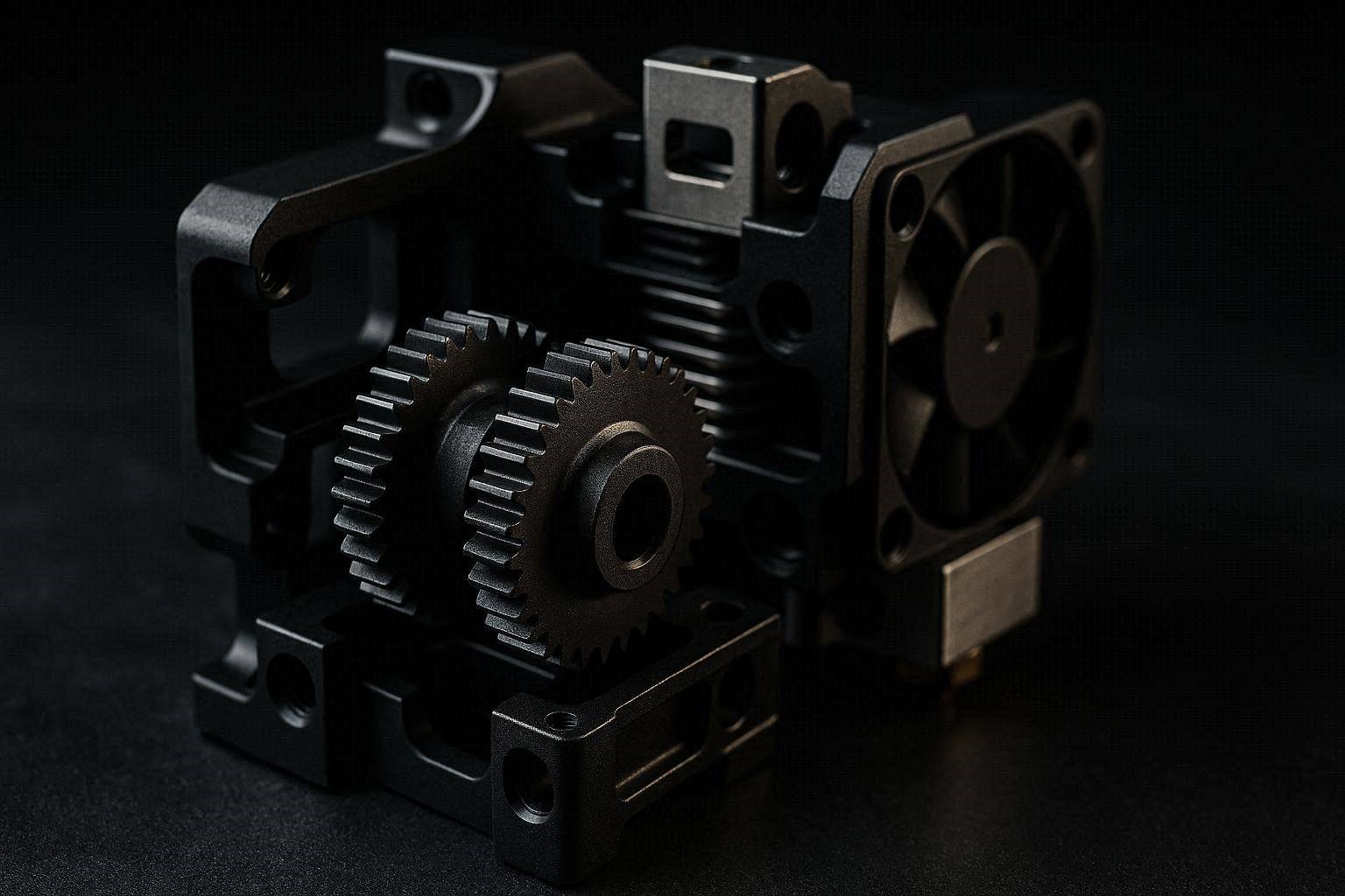
The standard upgrade path for modern high-performance printing involves retrofitting a complete dual-drive assembly. Leading manufacturers like Bondtech design specialized upgrade packages featuring precision-machined, hardened steel drive components.
These systems utilize a custom internal gear reduction ratio (such as 3:1 or 5:1). This mechanical gear reduction dramatically amplifies the rotational torque delivered by the stepper motor, allowing the extruder to push filament with massive force without requiring a large, heavy motor assembly.
You can source these professional dual-gear kits through enthusiast component hubs like MatterHackers. By upgrading to a hardened dual-drive layout, you ensure your extruder teeth maintain their sharp edge profiles even after consuming dozens of kilograms of abrasive carbon-fiber filled filaments.
Direct-Drive Conversion Toolheads
For older 3D printers that utilize a long Bowden tube setup, a 3d printer extruder gears upgrade is the perfect opportunity to transition to a modern direct-drive layout. Direct-drive configurations place the extruder assembly directly on top of the hotend heat block, reducing the physical distance between the drive gears and the nozzle down to a few millimeters.
Upgrading to an integrated system, such as a Creality Sprite or a premium Prusa toolhead assembly via specialized affiliate retailers, permanently eliminates the filament springiness issues inherent to long Bowden tubes.
This direct mechanical pairing allows for highly precise retraction control. You can drop your retraction length settings from 5.0mm down to a crisp 0.5mm, instantly shaving hours off complex print jobs while entirely preventing stringing, cobwebbing, and internal oozing failures.
[INTERNAL LINK: Placeholder for an article titled “First Layer Not Sticking? How to Fix 3D Print Warping & Spaghetti”]
[Extruder System Kinematic Performance Matrix]
+----------------------+--------------------+--------------------+
| Metric               | Factory Brass Single| Upgraded Hard Steel|
+----------------------+--------------------+--------------------+
| Maximum Pushing Force| 12 lbs - 15 lbs    | 35 lbs - 45 lbs    |
| Volumetric Limit     | ~ 10 mm³/s         | ~ 28 mm³/s         |
| Gear Wear Lifetime   | 150 - 200 Hours    | 2000+ Hours        |
| Flexible Filament Compatibility| Poor     | Excellent          |
+----------------------+--------------------+--------------------+
Essential Post-Installation Calibration: Tuning E-Steps
Once your new hardware is physically bolted into place, you must calibrate your printer’s firmware step-per-millimeter settings, commonly referred to as E-steps. Because your new upgrade gears likely feature a different pitch diameter or an internal reduction ratio compared to the stock parts, the printer’s computer currently has no idea how much motor rotation is required to move a millimeter of filament.
Skipping this step will lead to catastrophic print failures due to extreme over-extrusion or under-extrusion. Follow this highly precise volumetric calibration formula to synchronize your firmware with your new mechanical hardware.
The 100mm Extrusion Measurement Test
To compute your new E-step value, use a digital caliper or a precision ruler to measure exactly 120mm of filament starting from the entry lip of your extruder housing. Use a fine-tip permanent marker to place a sharp line on the filament casing at that exact 120mm mark.
Connect your printer to a terminal interface (such as OctoPrint, Pronterface, or the slicer’s built-in console window) and heat the nozzle to the standard operating temperature of your filament. Send the following G-code command sequence to set relative extrusion positioning and request exactly 100mm of fed material at a slow, controlled speed:
G91
M106 S0
G1 E100 F100
Once the extruder motor stops spinning, use your digital calipers to measure the physical distance remaining from the entry lip of the housing up to your permanent marker line. If your hardware is perfectly calibrated, exactly 20mm should remain unconsumed.
The Universal E-Step Scaling Correction Equation
If your remaining measurement is anything other than 20mm, you must calculate a custom firmware correction value. First, determine your current E-step value by sending an M503 command to the printer terminal and locating the line starting with M92 E. Use the following algebraic equation to calculate your new calibration step metric:
Enew=120−Lremaining100×Ecurrent
For instance, if your current E-step metric is set to 93, and your physical measurement shows 28mm of filament remaining outside the extruder, your actual consumed length was 92mm (120−28). Applying the mathematical equation yields:
Enew=92100×93=101.08
Send your new calibrated step metric to the printer firmware by executing the command M92 E101.09 (rounding to the nearest hundredth). Instantly lock this new metric into the printer’s permanent onboard EEPROM memory bank by executing an M500 save command, ensuring your custom settings persist even after cycling the master power switch.
Preventative Maintenance Checklist for Dual-Drive Extruders
To ensure your upgraded high-torque gear layout maintains its relentless grip and operates with absolute volumetric accuracy over thousands of hours, perform these quick structural check steps every month:
- Evacuate Debris Channels: Use a stiff-bristled nylon utility brush or compressed air to clean out the tooth tracks. Even dual-drive systems accumulate minor microscopic plastic skin scales over time, which fills the tooth valleys and reduces physical grip traction.
- Lubricate Transmission Gearing: Apply a micro-drop of premium synthetic PTFE grease to the main transfer gears that link the dual shafts together. Avoid using liquid oils, as they can migrate down the shafts and contaminate your filament line.
- Inspect Shaft Needle Bearings: Verify the secondary idler shaft spins freely without radial wobble. Worn internal needle bearings cause the gears to deflect under load, introducing subtle layer-line inconsistencies across your print finishes.
- Verify Stepper Mount Integrity: Check the tightness of the main structural fasteners securing the stepper motor block to the toolhead bracket frame. Extended periods of high-speed print directional changes can gradually back these screws out, leading to fatal toolhead shuddering.