9 Ways to Optimize Infill Patterns for High-Speed CoreXY 3D Printers
When you invest in a modern, high-acceleration CoreXY machine—such as a Bambu Lab X1C, a Voron, or a Creality K1—you are purchasing a kinematic system capable of moving a toolhead at 500+ mm/s and accelerating at 20,000 mm/s². However, this incredible speed capability exposes a fundamental mechanical flaw in how traditional slicing software handles internal geometry.
Most default slicing profiles are built on legacy logic designed for machines printing at 50 mm/s. When you apply those same logic patterns to a high-speed machine, you aren’t just printing; you are engaging in a high-velocity mechanical collision course. The primary culprit? Infill patterns that physically intersect with themselves.
In this comprehensive technical manual, we will deconstruct the mechanical resonance caused by improper infill geometry. We will analyze the physics of nozzle collisions, the necessity of non-intersecting structures, and how to calibrate your machine’s software to maintain high-speed structural integrity. Follow these 9 steps to correctly optimize infill patterns for CoreXY machines and ensure your prints succeed on the first attempt.
The “Quick Answer” / Key Takeaways Box
- The Collision Reality: Grid, Lines, and Triangles are “self-intersecting” patterns. The nozzle physically crashes into previously extruded plastic on every single layer, creating audible clicking, premature wear, and mechanical failure.
- The Gyroid Standard: Gyroid is the gold standard for high-speed CoreXY printing. It provides a non-intersecting, isotropic structure that distributes stress evenly and never forces the nozzle to cross its own path.
- Flow Rate Compensation: High-speed printing requires higher temperatures and adjusted flow multipliers. If your infill is under-extruding, your walls will eventually delaminate.
- Structural Modifiers: Do not print your entire model with high-density infill. Use “Infill Modifiers” in OrcaSlicer to only increase density in load-bearing areas, saving print time and reducing mechanical stress.
- Avoid Crossing Walls: Enable “Avoid Crossing Walls” (Combing) in your slicer to ensure the toolhead only travels over printed areas, hiding the inevitable minor oozing inside the model.
The Kinematic Physics of High-Speed Infill
To understand why you must optimize infill patterns for CoreXY printers, you must visualize the movement of your toolhead at 300+ mm/s.
Traditional infill patterns like “Grid” or “Rectilinear” are constructed by laying down a series of parallel lines in one direction, and then printing a second set of parallel lines at a 90-degree angle. Because these lines are printed on the same Z-height plane, the nozzle tip physically slams into the vertical ridges of the first set of lines every time it crosses them.
At low speeds, the hot nozzle can melt through these intersections. At high speeds, the toolhead is moving too fast for the nozzle to melt through the plastic. The nozzle tip effectively acts like a hammer, striking the plastic ridges. This generates an acoustic shockwave that travels through the gantry and into the motors, resulting in a distinct “buzzing” or “grinding” noise.
This mechanical hammering causes three fatal issues:
- Stepper Micro-Stalls: The force of the collision can temporarily overcome the holding torque of the stepper motor, causing it to skip steps (layer shifts).
- Reduced Belt Life: The constant vibration puts immense, unnecessary stress on your GT2 timing belts, leading to premature stretching and dimensional inaccuracy.
- Internal Tearing: The nozzle doesn’t just hit the infill; it drags it, causing internal structural voids that weaken the entire part.
Step 1: Standardize on Gyroid Geometry
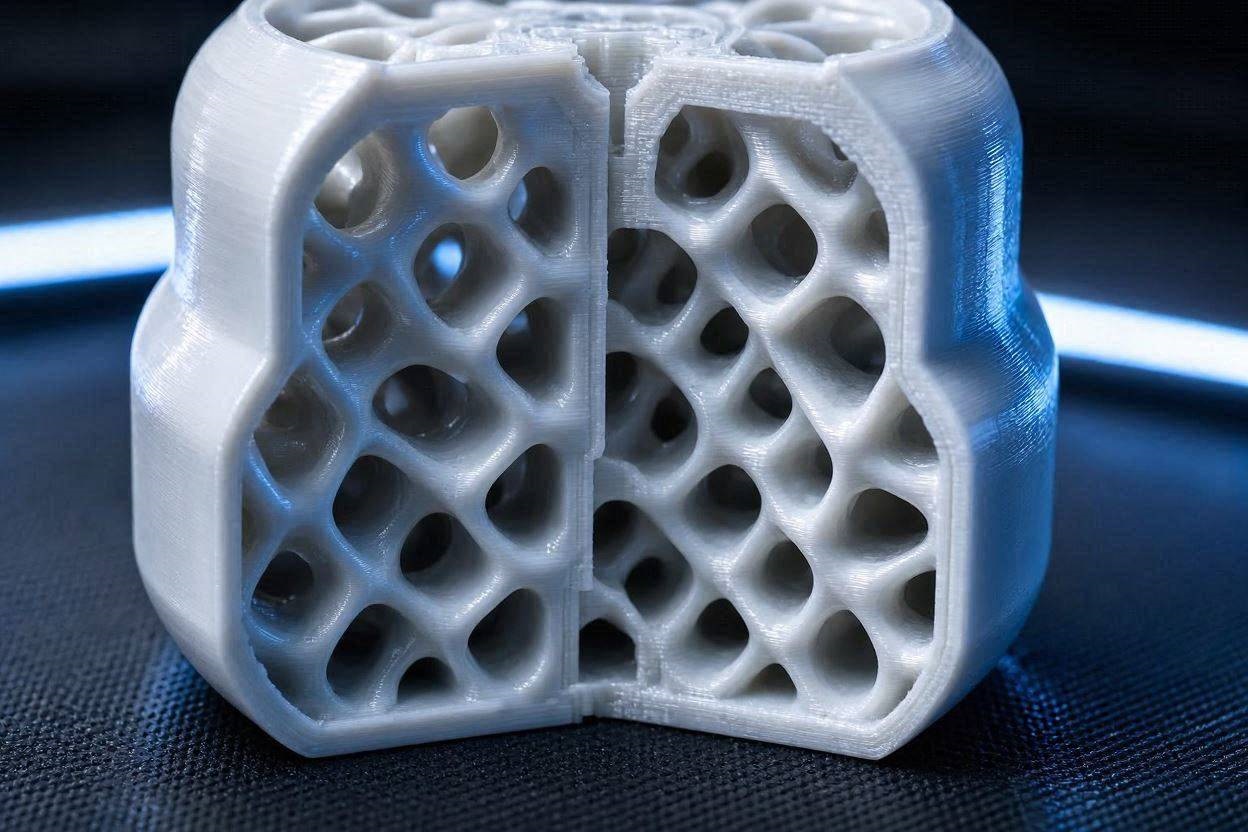
The first and most important step to optimize infill patterns for CoreXY is the total abandonment of intersecting patterns. Gyroid is the only infill pattern that is mathematically optimized for high-speed motion. It is a continuous, wave-like structure that never intersects itself on the same Z-layer.
Because the nozzle path is continuous and curved, the toolhead never makes a sharp 90-degree turn or strikes a vertical plastic ridge. This reduces vibration, lowers the noise floor of your printer, and significantly increases the structural strength of the part.
Step 2: Tuning Wall-to-Infill Overlap
Even with a non-intersecting pattern like Gyroid, you must ensure the infill actually bonds to your outer walls. In Bambu Studio or OrcaSlicer, the “Infill/wall overlap” setting defines how much the infill path encroaches into the perimeter walls.
If the overlap is too low, your infill will be weak and separate from the shell. If the overlap is too high, the infill will push plastic outward, creating visible “pillowing” or bulges on the outer walls of your model. A value of 15% to 20% is the optimal “Goldilocks” zone for most high-speed filaments.
Step 3: Implementing Regional Infill Modifiers
Printing an entire part with high-density infill is a waste of mechanical resources and time. It creates excessive internal nozzle pressure and increases the chance of structural failure.
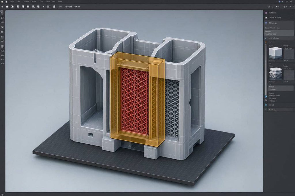
Use Infill Modifiers in your slicer. By right-clicking your model and adding a “Box” or “Cylinder” modifier, you can define a specific zone inside your model that requires higher infill density (e.g., 40%) while keeping the rest of the model at a sparse density (e.g., 10%). This optimizes structural strength where you need it most while maximizing the speed capabilities of your CoreXY motion system.
Step 4: Speed Capping for Infill
You do not need to print infill at the same speed as your outer walls. In fact, you shouldn’t.
Infill is internal; it does not need to be aesthetically perfect. However, printing infill too fast causes the extruder to lose pressure, leading to “sparse” or “weak” infill that doesn’t actually connect to the walls.
Set your Infill Speed to approximately 70-80% of your max wall speed. This gives the extruder sufficient time to build up the pressure required to lay down solid, continuous lines that fully bond to the perimeter shells.
Step 5: Adjusting Flow Rate for Infill
High-speed extrusion often requires a slightly higher extrusion multiplier (flow rate) to account for the pressure drop inside the nozzle.
If you notice your infill is stringy or disconnected, perform an Extrusion Flow Calibration specifically for your filament brand. A perfectly calibrated flow rate ensures the infill is thick and robust, which is vital for the structural longevity of high-speed prints.
Step 6: Utilizing “Avoid Crossing Walls” (Combing)
To further optimize infill patterns for CoreXY motion, you must control how the toolhead moves between infill islands. Enable the Avoid Crossing Perimeters (or “Combing”) setting.
When enabled, this forces the toolhead to travel exclusively over printed areas, rather than jumping over empty space. While this increases total print time, it ensures that any minor, unavoidable ooze is deposited on top of the infill, keeping your outer shell surfaces clean and professional.
Step 7: Top Surface Layer Thickness
When printing with sparse infill (e.g., 10-15%), the top layers have to bridge across large gaps. If you only print 2 or 3 top layers, the plastic will sag into the infill, creating a “pillowed” or bumpy finish.
To resolve this, increase your Top Shell Layers to 4 or 5, ensuring a minimum thickness of at least 0.8mm. This provides a rigid, flat surface for the printer to build upon, preventing the internal infill structure from telegraphing through the final print.
Step 8: Tuning Acceleration for Internal Geometry
Acceleration is the enemy of consistent extrusion. When the toolhead is traveling inside the model printing infill, you do not need the same acceleration settings you use for the outer visual walls.
In your slicer’s Acceleration tab, explicitly set the Infill Acceleration to be 20-30% lower than your Outer Wall Acceleration. This reduces the mechanical “jerk” on the infill structure, allowing the extruder to maintain a more consistent pressure throughout the internal geometry.
Step 9: Infill Line Width Optimization
For structural models, increasing the Infill Line Width can provide significantly higher strength than simply increasing the infill density.
If you are using a 0.4mm nozzle, try increasing your Infill Line Width to 0.45mm or 0.5mm. This creates a thicker, sturdier internal grid that bonds more effectively to the inner walls, providing superior structural rigidity without significantly increasing your total print time.
The Permanent Fix: Quality Upgrades
Optimizing your software kinematics is the first step, but a CoreXY machine is only as fast as its weakest physical component. If you are operating a production print farm, relying on stock hardware to maintain extreme speed will lead to mechanical failure.
1. Upgrade to a High-Flow CHT Nozzle
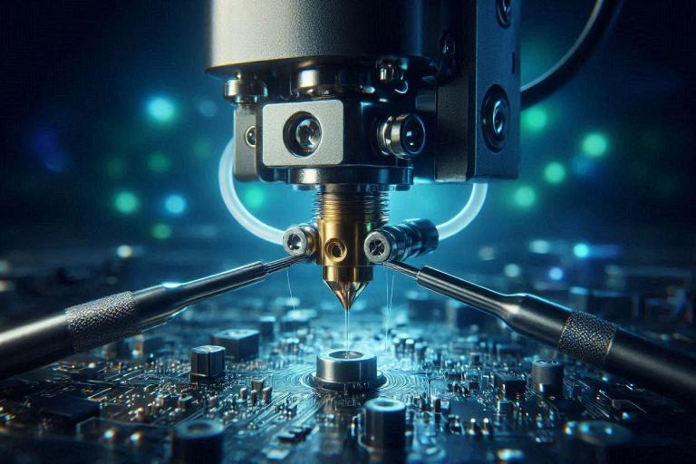
Standard brass nozzles fail at high volumetric speeds because the plastic core remains solid. CHT (Core Heating Technology) Nozzles are mandatory for high-speed optimization. They use internal copper splitters to triple the heated surface area, ensuring your polymer is fully molten before it leaves the tip. Sourcing these through the MatterHackers or ShareASale affiliate networks permanently raises your printer’s volumetric ceiling.
2. Install High-Precision Linear Rails
Budget linear rods vibrate under the high-frequency harmonics of CoreXY travel moves. Upgrading to genuine Hiwin MGN12H linear rails creates a rigid, high-precision motion path that does not flex under rapid acceleration. You can source these through industrial partners on MatterHackers to ensure your gantry remains square and vibration-free at any speed.
3. Active Filament Desiccation
All infill optimization is invalidated if your filament is wet. Moisture creates steam explosions that cause internal structural gaps. Invest in an active, heated filament dryer like the Sunlu S4 to bake your filament at 50°C during the print. Active drying via the Impact affiliate network is the only way to guarantee that your high-speed extrusion remains solid and consistent.
[IMAGE PLACEHOLDER: A professional studio photograph of a high-speed printer toolhead featuring a CHT nozzle and a direct-feed filament dryer + Alt Text: Upgrading your extrusion ecosystem to optimize infill patterns for CoreXY and maximize reliability.]
Preventative Maintenance Checklist
- Acoustic Belt Tuning: Pluck your belts monthly. Unequal tension is the primary cause of CoreXY inaccuracy.
- Lubricate Linear Rails: Use high-grade PTFE synthetic grease every 200 hours to prevent carriage binding.
- Torque Check: The vibration from high-speed infill can back out frame screws. Tighten the chassis fasteners monthly.
- Cold Pull Purging: Run a nylon cold pull weekly to clear carbonized buildup from your nozzle, which is the leading cause of internal pressure spikes.
By shifting from self-intersecting grid patterns to Gyroid, and locking down your acceleration and flow mechanics, you turn your high-speed printer from a noisy vibrating machine into a consistent manufacturing asset. Optimize infill patterns for CoreXY motion, eliminate mechanical collisions, and start producing parts with absolute geometric integrity.
One Comment